Remove the inner casing cover. Refer to Section 15.3.(b).
If the air/flue duct assembly is to be fitted from inside the building then
the ducts must be cut to length, assembled and inserted through the
wall now before fitting the flue elbow to the appliance. Refer to Section
12.10 following after the assembly of the flue ducts.
12.8 Air and Flue Duct Preparation.
The method of installation of the flue system may be varied to suit the
actual site conditions. The instructions for connecting and fixing the
ducts must, however, be strictly followed.
Unpack the flue spigot, restrictor ring and clamping rings from the
Flue Spigot Kit in the boiler Installation Pack. Fit the spigot to the
boiler top panel with the four screws provided in the Flue Spigot Kit.
IMPOR
TANT Check the maximum flue length and if it is less than 1m
total overall length then fit the restrictor ring as shown in Fig. 18.
24CDi 75mm Horizontal flue up to 1m
28CDi 77mm Horizontal flue up to 1m
35CDi II 85mm Horizontal flue up to 1m
The standard uncut telescopic flue assembly is suitable for flues from
425mm up to 725mm measured from the centre-line of the boiler flue
outlet to the outer face of the wall. Refer to Fig.19 & 20.
If L>725mm then extension duct kit/s will be required - each kit
14
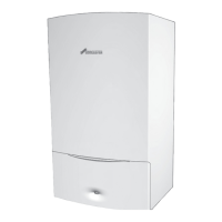
Fig. 17. Fixing the appliance to the wall mounting plate.
Wall mounting plate
Appliance
Keep appliance
vertical
Step 1. Rest appliance on
wall mounting plate and push
back, engaging valves first.
Step 2. Secure at top
with the M6 nuts and
washers supplied (2).
Step 3. Secure
at bottom with
caps and bolts
supplied (3).
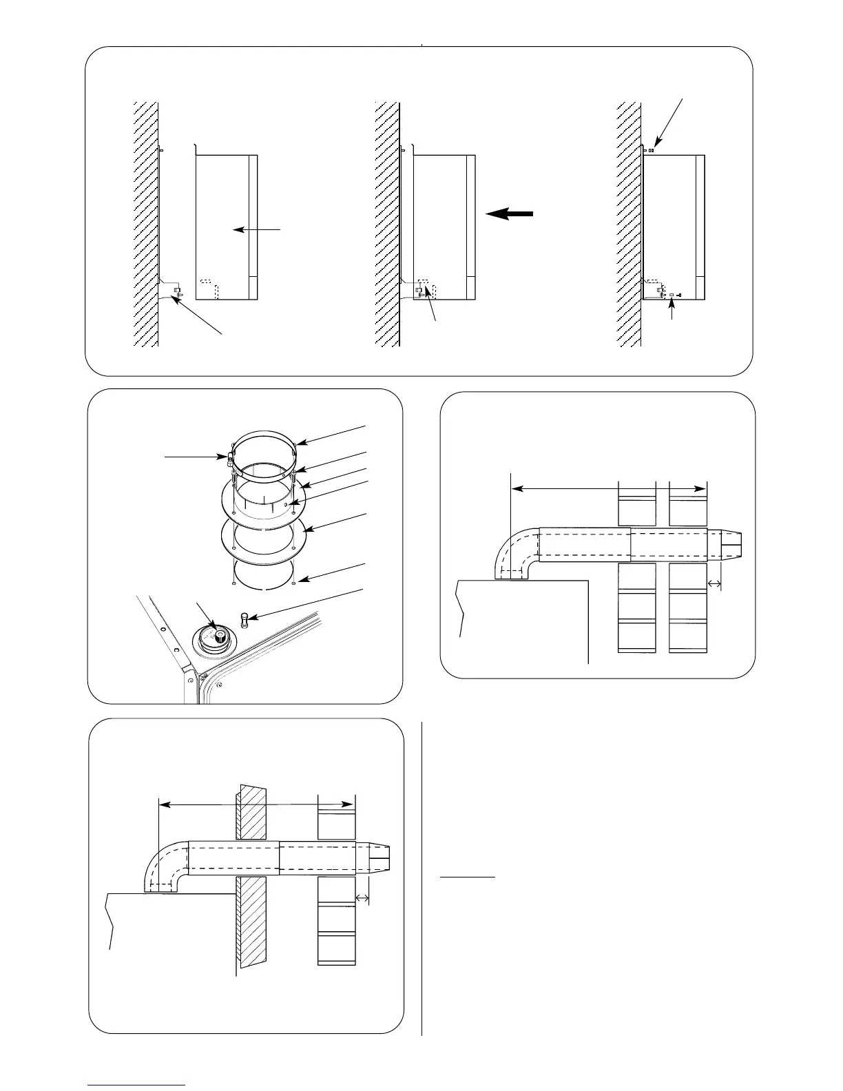
Fig. 18. Flue turret fixing and automatic
air vent.
Fig. 19. Flue duct length (rear flue).
Fig. 20. Flue duct length (side flue).
1
2
3
4
5
6
1.Flue spigot fixing screws
2.Flue spigot
3.Restrictor ring
4.Flue spigot fixing holes
5.Combustion sensing
point
6.Automatic air vent
7.Clamping ring
8.Fixing screw hole
Rear face of appliance
and face of mounting
wall
External
wall face
40mm
L
L
Flue
Turret
assembly
Terminal
assembly
40mm
1
7
8