extends the flue by 750mm up to a maximum of 4m. See table below.
EXTENSION MAXIMUM FLUE LENGTH mm
24CDi 28CDi
35CDi II
1 1475 1475 1475
2 2225 2225 2225
3 2975 2975 2975
4 3725 3000 3000
5 4000
12.9 Measure and Cut the Ducts.
General
: Cut the ducts as necessary, ensuring that the ducts are square
and free from burrs. Always check the dimensions before cutting.
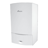
Measure the distance L. Refer to Fig.19 and 20.
The standard flue can be telescopically adjusted to any length between
425mm and 725mm.
Fix the flue assembly together using the self-tapping screws provided.
Refer to Fig.21.
It will only be necessary to cut the standard assembly if L<425mm.
Cut the flue turret assembly and
the terminal assembly by the same
amount i.e L=350 - remove 75mm from each
assembly.
Minimum side flue length = 335mm (accommodating a 10mm
Service clearance and a 100mm wall)
Minimum rear flue length = 297mm (accommodating a 100mm wall)
24CDi 28CDi/35CDi II
If L is between 1175 - 1475mm 1175 - 1475mm (1 extension)
1925 - 2225mm 1925 - 2225mm (2 extension)
2675 - 2975mm 2675 - 2975mm (3 extension)
3425 - 3725mm N/A (4 extension)
it is not necessary to cut the ducts.
24CDi 28CDi/35CDi II
If L is between 725 - 1175mm 725 - 1175mm (1 extension)
1475 - 1925mm 1475 - 1925mm (2 extension)
2225 - 2675mm 2225 - 2675mm (3 extension)
2975 - 3425mm 2975 - 3000mm (4 extension)
3725 - 4000mm N/A (5 extension)
It is necessary to shorten the assembly by cutting the first extension
duct assembly i.e. L = 1000mm - remove 175mm from the air and flue
ducts.
NOTE: Extension duct measurements do not include the socketed end.
Unless specifically instructed the socketed end must not be removed.
Fix the flue ducts together before fixing the surrounding air duct, the
cut ducts fit into the flue assembly.
12.10. Fitting the Flue Assembly with Access to the Terminal.
Prepare the flue duct assembly as described in Section 12.9.
Apply the plastic tape to the air duct in contact with the external
brickwork.
From inside push the assembly through the wall. Align the flue turret
and push fully onto the spigot on the appliance. Tighten
the clamping ring and fix using the screw provided. Refer to Fig.24.
Make good the internal wall face and the external brickwork or
rendering.
Replace the inner casing.
12.11 Fitting of the Flue Assembly without access to the Terminal.
NOTE: A larger diameter opening in the wall is required. Refer to Table 2.
Prepare the flue assembly as described in Section 12.9.
Fit the rubber sealing gasket centrally onto the terminal assembly and
tighten the clamp. Refer to Fig. 23.
Apply the plastic tape to the air duct in contact with the external
brickwork.
From inside push the assembly through the wall so that the
gasket flange is against the outer face. Refer to Fig. 23.
It may be necessary to adjust the legs of the flue centring ring.
Align the flue turret and push fully onto the socket on the appliance.
Tighten the clamping ring and fix using the screw provided. Refer to Fig 24.
Seal the gap around the duct at the inner wall face and make good.
Replace the inner casing.
15
Fig. 21. Flue turret, ducts and terminal
assembly
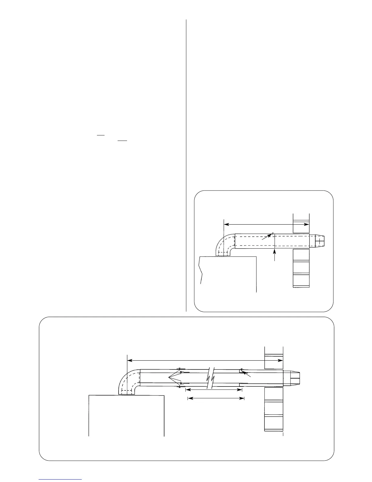
Fig.22. Flue assembly using extension kits.
L
Appliance casing
Fixing screws Fixing screw
Turret
assembly
Terminal
assembly
Ducts of equal length
Shorten first extension fitted
to the turret assembly if more
than one extension is fitted
Appliance casing
Fixing screw
Turret
assembly
Terminal
assembly
L
Telescopic
adjustment