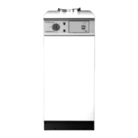
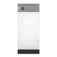
21
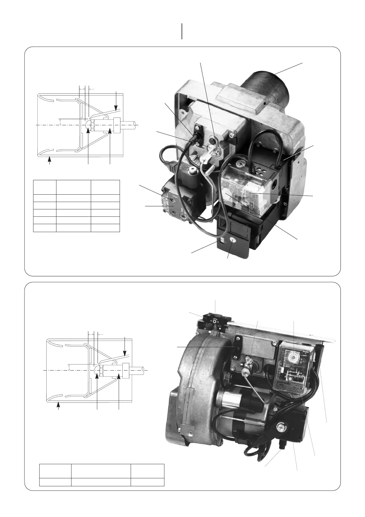
Fig. 22. Electro Oil Inter B11 Burner.
(20/25 model).
Combustion Head
Air control indicator
Photocell
Air adjustment screw
(4 mm hexagonal head)
Transformer
Control box
Oil pump
Pressure
adjustment
screw
Draught tube
Nozzle Nozzle block
Spark gap
3-3.5 mm
2 mm
10 mm
A
Lockout
reset button
Pressure
gauge port
Output
Combustion Head
Dimension
kW A
20/25 PL 10/4/24/10 x 78 mm 5 mm
Fig. 21. Electro Oil Inter B9 Burner.
(12/14 and 15/19 models)
Combustion Head
Draught tube
Nozzle Nozzle block
Spark gap
2-2.5 mm
2 mm
10 mm
A
Combustion head
Locking screw
Transformer
Photocell
Control box
Lockout reset button
Air adjustment screw
(4mm hexagonal head)
Air control indicator
Oil pump
Pressure Adjustment
Screw
Adjusting
disc
Output Dimension
kW Head Type A
12
PL 6/7/21.5/10 3 mm
14 PL 6/7/21.5/10 5 mm
15 PL 6/7/21.5/10 3 mm
17 PL 6/7/21.5/10 5 mm
19 PL 6/7/21.5/10 5 mm
To adjust the nozzle position, undo the
locking screw located at the rear of the
nozzle line and rotate the adjusting
disc one turn anti-clockwise to move
forward by 1 mm.
2.20 Add a suitable proprietary corrosion inhibitor such as
Fernox or Sentinel. This will inhibit corrosion, protect the circu-
lating pump and valves reducing the possibility of "kettling"
noises resulting from deposits of scale and sludge in the boiler.
Refer to the product manufacturers instructions for further infor-
mation.
 Loading...