9
A flue system must be provided in accordance with BS5410:Part
1 and the Building Regulations, Part J, Section J2.
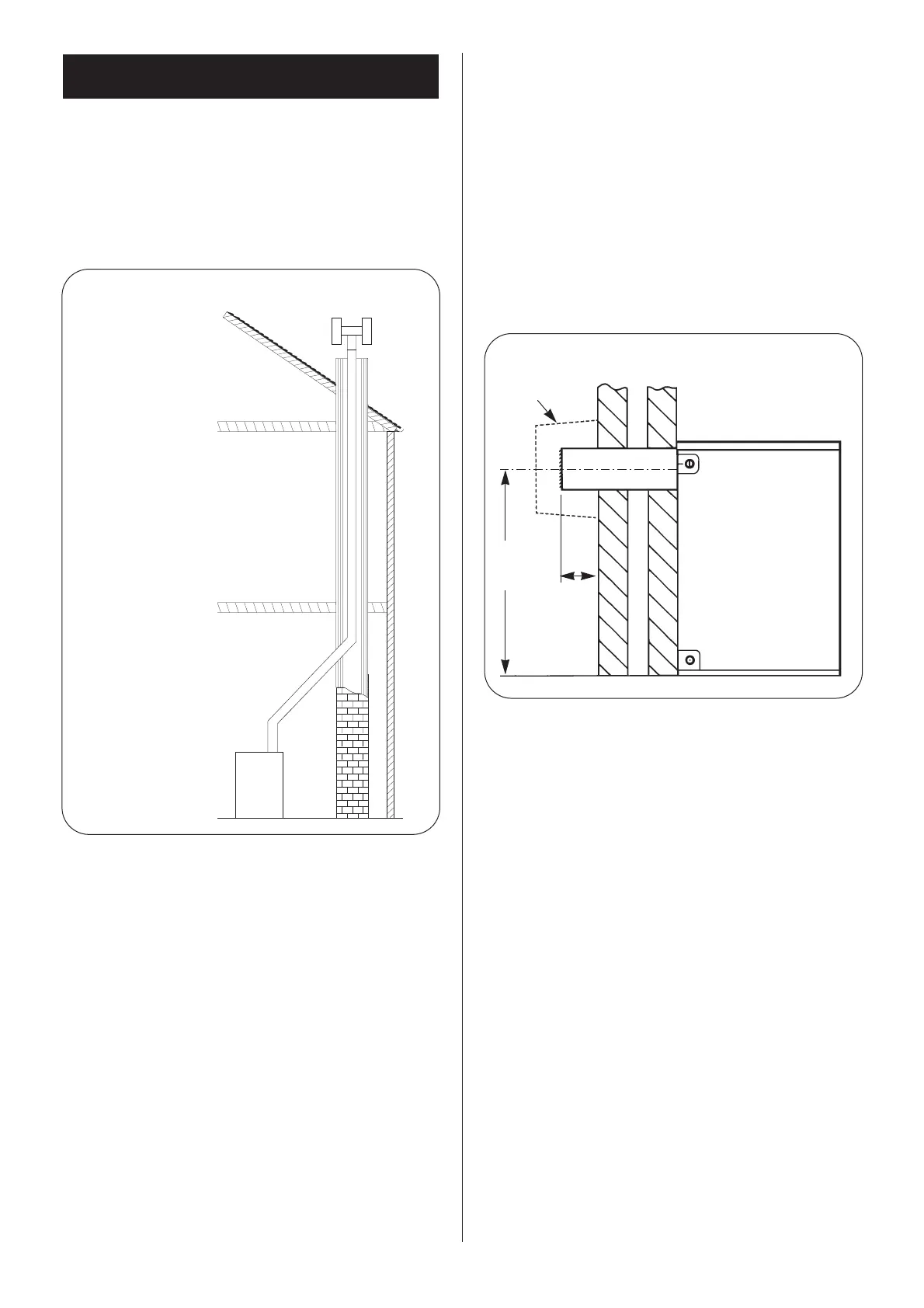
7.1 CONVENTIONAL FLUE (CF).
See Fig. 4.
Conventional Flue Diameters: 12/14 – 100 mm (4 in.)
15/19 – 100 mm (4 in.)
20/25 – 100 mm (4 in.)
26/32 – 125 mm (5 in.)
32/50 – 125 mm (5 in.)
50/70 – 150 mm (6 in.)
The boiler is fitted with a conventional flue locating spigot. The
flue pipe fits into the spigot and should be correctly sealed with
fire cement.
NOTE: The size of the flue must never be reduced from the take-
off diameter. An increase in flue size is permissible provided that
the joint is sealed correctly.
When installed the flue should be vertical and contain as few
bends as possible. Where bends are necessary, a maximum of
two are permitted and 135 degree bends should be used.
All brick and masonry chimneys should be lined with a suitable
non-combustible material, properly jointed and able to with-
stand the effects of the working temperature of the appliance
and any condensate which may form.
Down-draught conditions will adversely affect the operation of
the boiler and must be avoided. Where possible the flue should
be extended beyond the apex of the roof and should always be
taken beyond the eaves of the building. Where down-draught is
experienced a suitable anti down-draught terminal should be
fitted to the flue termination.
The natural flue draught must be checked in the flue pipe imme-
diately above the appliance or in the hole provided in the flue
outlet plate. The flue draught should be no less than 0.75 mm
W.g. and no greater than 5.1 mm W.g. If a flue draught greater
than 5.1 mm W.g. is experienced a draught stabiliser should be
introduced into the flue and adjusted to achieve a flue draught
within the specified range.
7.2 Low Level Discharge
(See Fig. 5).
The conventional flue appliance may be converted to discharge
the products of combustion at low level. For this purpose a spe-
cial flueless kit and associated ducting is available, allowing the
conventional flue to be discarded. Detailed instructions for con-
verting the appliance to low level discharge are supplied with
the conversion kit. The flue spigot should be removed from the
flue outlet plate by undoing the three retaining screws and the
hole blanked off with the plate provided in the kit.
NOTE: Under no circumstances may 35 Second Gas Oil be
burned with this type of flue terminal arrangement.
7.3 ROOM SEALED BALANCED FLUE MODEL (RS).
The appliance is supplied ready for installation as a low level
discharge balanced flue system by the simple addition of one of
the flue terminal kit options shown in Fig. 6.
Details of the installation procedure are included in the Flue
Terminal Instructions supplied with the terminal kit.
Alternatively, a range of room sealed balanced flue kits are avail-
able to convert the appliance to discharge the flue products to
the left, right, at a higher level, or vertically up to a roof height of
4.5 metres.
7.4 Siting the flue terminal
1. The flue terminal must be located in a suitable position, as
shown in Fig. 7, such that the products of combustion can be
freely dispersed without the possibility of the gases entering the
dwelling or that of a neighbouring dwelling.
2. Discharge of flue gases into car ports or narrow passageways
is not recommended.
3. The terminal must not cause an obstruction nor the discharge
cause a nuisance as a result of either flue gases or terminal
noise.
4. If the terminal is fitted within 1 m of a plastic or painted
gutter or within 500 mm of painted eaves then an aluminium or
stainless steel shield at least 1 m long should be fitted to protect
the surface.
5. If a terminal is fitted less than 2 metres above a surface to
which people have access, fit a terminal guard as shown in Fig. 8.
A suitable guard is available from Worcester Heat Systems, Part
Number 7 716 190 009, or alternatively a proprietary terminal
guard may be used provided it has the minimum dimensions
shown in Fig. 8.
The guard should have suitable corrosion resistance due to the
acidic content of the flue gases.
7. Flue System
Fig. 4. Flue Installation.
Where possible take the
flue above the apex – if not
above the apex an anti
down-draught terminal is
advisable.
Brick Chimney.
Use of a flue liner
is recommended.
Use as few bends as
possible.
Use 135° Bends.
Flues must not be reduced from
the boiler take off diameter.
ALWAYS TAKE THE FLUE ABOVE THE EAVES
Fig. 5. Flue Installation (Rear Discharge).
See Fig. 7 for
flue terminating
positions.
80
min.
FLUE GUARD
766
 Loading...