14
9.1 The appliance is suitable for connection to all conventional
indirect hot water systems utilising an indirect double feed
cylinder.
9.2 The flow and return sockets are located at the rear of the
appliance, two at high level (flow) and two at low level (return).
Connection of the flow and return sockets can either be made on
diagonally opposite sockets or on the same side of the boiler.
9.3 Provision has been made for locating the circulating pump
within the appliance cabinet. If so required, the socket located in
the top front of the boiler should be used and the flow pipe run
either side of the boiler (See Figs. 2 and 3).
9.4 There is no requirement for a system bypass.
9.5 The pressure jet burner fitted to the appliance has full
automatic control and hence there is no requirement for heat
leak radiators.
9.6 Any unused boiler tappings should be plugged prior to
filling. It should be noted that the flow tapping on the front of
the boiler requires plugging when not used.
9.7 The primary system should be flushed and treated in
accordance with the recommendations of BS 7593:1992 before
the system is handed over to the user.
9.8 The pump should be set in accordance with the heating load
requirements to give a flow and return differential temperature
of 11°C under full load conditions.
Open Vent Primary System.
(See Figs. 12 and 13).
The following points are for guidance only. The system
installation should be carried out in accordance with BS 5449:
Part 1.
1. Feed and Expansion System
The feed and expansion pipes must rise continuously from the
appliance and must be of the minimum diameter shown in Figs
12 and 13.
The cistern must be arranged to provide a minimum static head of
1 metre above the top of the highest point in the heating circuit.
2. Filling and Venting
Air in the appliance is expelled through the vent pipe or
dissipated into the system. Manual air vents should be fitted at
any high points in the system.
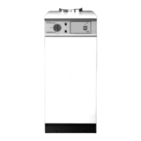
9. Heating and Hot Water System
Fig. 12. Typical Open Vent Gravity Primary System.
Feed and
Vent Cistern
Primary cold
feed (15mm min.)
Primary cold
feed (15mm min.)
Heating vent
(22mm min.)
Heating vent
(22mm min.)
Boiler
Pump
Radiator
S.H. – Minimum static head 1m (3ft)
measured from the top surface of the
appliance or highest point in the
heating system to the water level in
the feed and expansion tank
N.B. A drain cock should be
installed at the lowest point
of the heating circuit
Domestic
hot water
cylinder
S.H.
S.H.
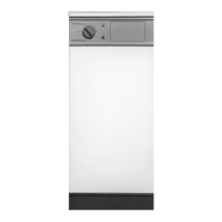
Fig. 13. Typical Open Vent Fully Pumped System (Honeywell ‘Y’ plan).
Feed and
Vent Cistern
Diverting
valve
Boiler
Pump
Radiator
S.H. – Minimum static head 1m (3ft)
measured from the top surface of the
appliance or highest point in the
heating system to the water level in
the feed and expansion tank
N.B. A drain cock should be
installed at the lowest point
of the heating circuit
Domestic hot
water cylinder
S.H.
S.H.
 Loading...