ITEMS SUPPLIED WITH UNIT
6 720 648 720 (2011/07)
6
3 ITEMS SUPPLIED WITH UNIT
CASCADE FRAME (Æ FIG. 1)
• Supports
• Connecting frame
• Main gas pipe
• Flow and return header
• Boiler connection kit
• Flange seals
• Low loss header
• Blank flanges
• Rubber pump seals
• Fixings
• Installation instructions.
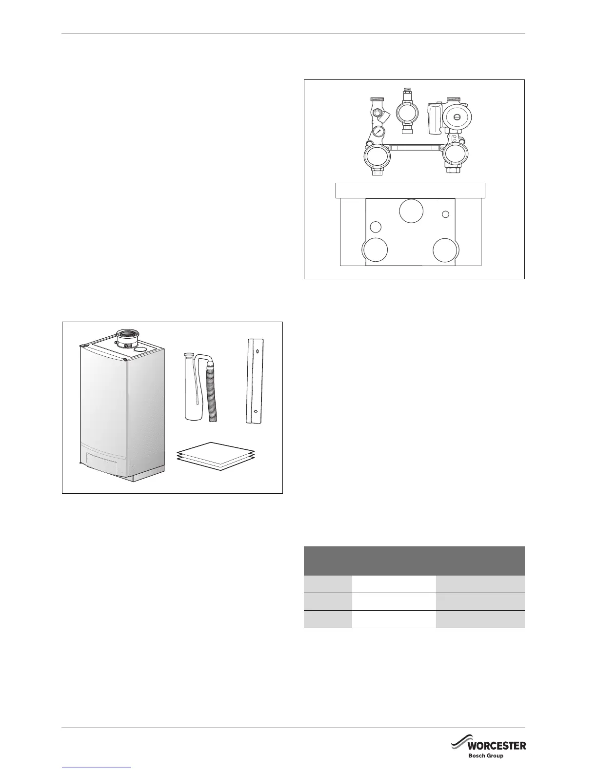
BOILER (Æ FIG. 2)
(TO BE ORDERED FROM YOUR SUPPLIER)
• Mounting bracket
• Boiler
• Siphon
• Installation instructions.
Fig. 2 Items supplied with the boiler assembly
PUMP GROUP (Æ FIG. 3)
(TO BE ORDERED FROM YOUR SUPPLIER)
• Connection kit
• Installation instructions.
The connection kit consists of:
• Maintenance valves
• Drain cock
• Gas isolation valve
• Pressure relief valve
• Non-return valve
• Pump
• Pressure gauge.
Fig. 3 Items supplied with pump group
Worcester supplies cascade systems in TL and TR
configurations:
TL: INLINE INSTALLATION
All boiler assemblies are in a line enabling an easy-to-
monitor installation in a narrow room.
TR: BACK-TO-BACK INSTALLATION
The boiler assemblies are located on both sides of the
frame and are installed back-to-back to create a compact
installation which ideally suits rectangular rooms and
which ensures the best possible access to all boilers.
Depending on the desired output, a choice can be made
between different types.
BOILER ASSEMBLY CONNECTION KIT
The connection kit can be used for the 65-kW, 80-kW and
100-kW version. The connection kit includes a pressure
relief valve, a non-return valve, a pump and isolating
valves.
6 720 648 720-001.1TD
Low loss
header
TL-configuration
(inline)
TR-configuration
(back-to-back)
2½" TL2, TL3 TR2
3" TL4 TR3, TR4
4" TL5, TL6, TL7, TL8 TR5, TR6, TR7, TR8
Table 2 Low loss header configuration
6 720 648 720-002.1TD