PRE-
IN STALLATION
INSTALLATION & SERVICING INSTRUCTIONS FOR WORCESTER BOSCH
16
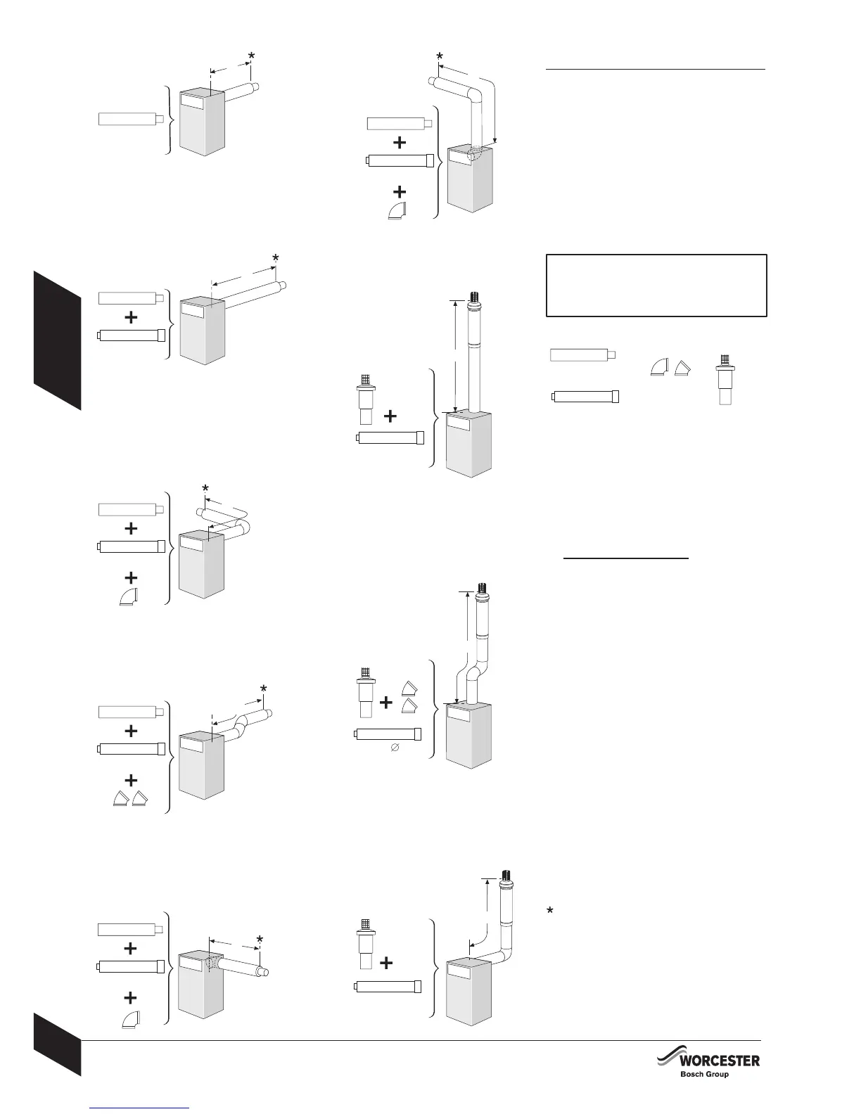
ROOM SEALED FLUE OPTIONS
8-716-106-256a (08.05)
ROOM SEALED FLUE OPTIONS
The diagrams (opposite) show the components
used and the maximum flue length (L) for each
flue configuration.
To achieve the maximum flue length (L), a flue
section will have to be reduced in length.
Only the flue terminal or straight flue extensions
can be reduced in length by cutting.
The flue terminal end can be fitted from the
inside or outside of the building.
IMPORTANT:
All horizontal sections must rise away from
the boiler by 52mm per metre (3°) to allow
the condensate to drain back to the boiler.
A - Horizontal terminal
B - Straight flue extension
C - Flue bend 90°
D - Flue bend 45°
E - Vertical Terminal Kit (incl. 90° elbow)
Calculating the flue length:
Measure the total flue length required, noting that
the
maximum straight flue length including the
terminal is:
Horizontal 80/125mmØ: 4000mm (excluding
120mm of terminal extending outside the building).
Vertical 80/125mmØ: 6000mm (including the
vertical flue kit 90° elbow).
Then reduce the total straight flue length for each
extra flue bend (excluding the vertical flue kit 90°
elbow) by:
1000mm for 90°
500mm for 45°
Flue Extension lengths:
Horizontal & Vertical 80/125mmØ: 1000mm overall
length.
Effective length when engaged into sockets within
the flue run is 950mm.
Flue Terminal lengths:
Horizontal 80/125mmØ: 720mm
Vertical 80/125mmØ: 1080mm + cage.
to outside wall.
E
E
E
E
L = 5000mm
125mmØ x5
L
B
L = 5000mm
125mm
x4
L
D
D
B
L = 6000mm
125mmØ x6
L
B
L
L = 2000mm
125mmØ x2
C
B
A
L = 140 - 390mm
L
A
L = 4000mm
125mmØ x4
L
B
A
L
L = 3000mm
125mmØ x3
C
B
A
L = 3000mm
125mmØ x3
L = 3000mm
D D
B
A
L
125mmØ x3
B
A
C
L
B
C
D
A
x2