COMMISSIONING
INSTALLATION & SERVICING INSTRUCTIONS FOR WORCESTER BOSCH
STARTING THE APPLIANCE
31
STARTING THE APPLIANCE
8-716-106-256a (08.05)
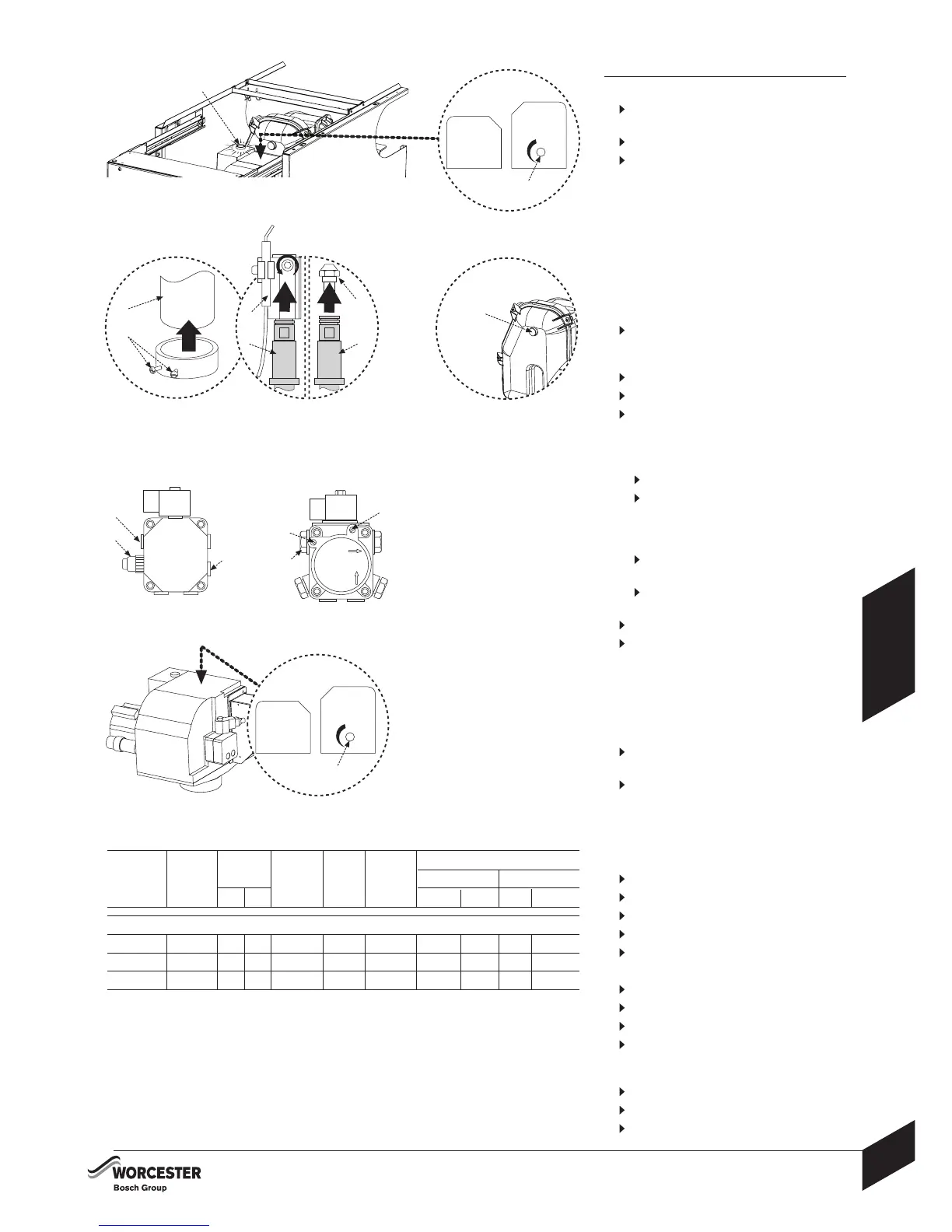
2 Fit a suitable pressure gauge to port (A) on
the oil pump.
Remove plastic cover from the burner casing.
Adjust the air shutter (L) and pump pressure
(B) as shown in the table opposite. The burner
should ignite following a pre-ignition period of
approx. 15 seconds.
Boiler lockout indicator on:
If the burner fails to establish a normal firing pattern
or flame failure occurs the flame monitoring photocell
mounted in the burner body will alert the burner
control box to shut the burner down and provide
a safe lockout state indicated by the illumination
of the lockout indicator (E).
Wait 2 minutes then press the lockout
indicator/reset button (E) to initiate another start
sequence.
Repeat procedure until a flame is established.
3
Start and run for 3 minutes then switch off.
Check for after-spurting from the nozzle,
indicated by oil saturation on the combustion
head (F).
If after-spurting occurs:
Release the burner retainers (G).
Remove the burner, combustion head (F)
and electrodes (M), hold the burner vertical
to unscrew the nozzle (H) and fill the nozzle
holder (J) with oil.
Refit nozzle (H), electrodes (M), combustion
head (F) and the burner.
Restart and run for 3 minute intervals until
after-spurting stops.
4
Start and run for 20 minutes.
Remove sampling point plug (K) to check the
smoke reading is between 0-1. If the smoke level
is above 1, check the combustion settings are
correct and the oil nozzle is in good condition.
Note; smoke readings may be inaccurate until
the smoke from burning organic binder in the
access door insulation has ceased.
Check the CO
²
levels and adjust the air shutter
(L) setting according to the table opposite.
Check the flue gas temperature is close to the
values shown in the table.
If the flue gas temperature is too high and the
baffles are correctly fitted, then reduce the oil
pump pressure (B) 5-10p.s.i. to compensate
for nozzle variations.
Turn off the electrical supply.
Isolate the oil supply to the burner.
Remove the oil pressure gauge.
Refit the blanking plug (A).
Check and rectify any oil leaks.
5
Switch on the oil supply.
Switch on the electrical supply.
Restart the boiler and run for 5 minutes.
Recheck the CO
²
levels and if required, adjust
the air shutter setting (L) according to the table
opposite.
Repeat the fine tuning procedure (5) if required.
Refit the sampling point plug (K).
Refit plastic cover to burner casing.
%CO
2
NOMINAL BOILER RATING AT NORMAL OPERATING TEMPERATURE
USING 28sec KEROSENE:
NOZZLE
Bentone Sterling 50 Burner:
OIL PUMP
PRESSURE
(p.s.i.)
FUEL
FLOW RATE
Kg/h l/h
APPROX.
FLUE GAS
TEMP °C
APPROX.
AIR
SETTING
APPLIANCE
INPUT OUTPUT
kW Btu/hr kW Btu/hr
0.50 80°EH
0.55 80°EH
0.65 80°EH
130
145
150
1.56
1.86
2.17
1.98
2.36
2.75
72
79
82
11.5
12.0
12.5
4.25
6.00
8.00
63300
75100
87900
18.0
21.5
25.0
61400
73400
85300
18.6
22.2
25.8
DANFOSS
BFP 11 L3 OIL PUMP
SUNTEC
AS47C OIL PUMP
E
4
5
L
J
A
B
C
A
B
C
A - Bleed & pressure gauge port
B - Pressure adjustment
C - Vacuum gauge port
L
2
3
F
M
H
G
J
K