Fig
.
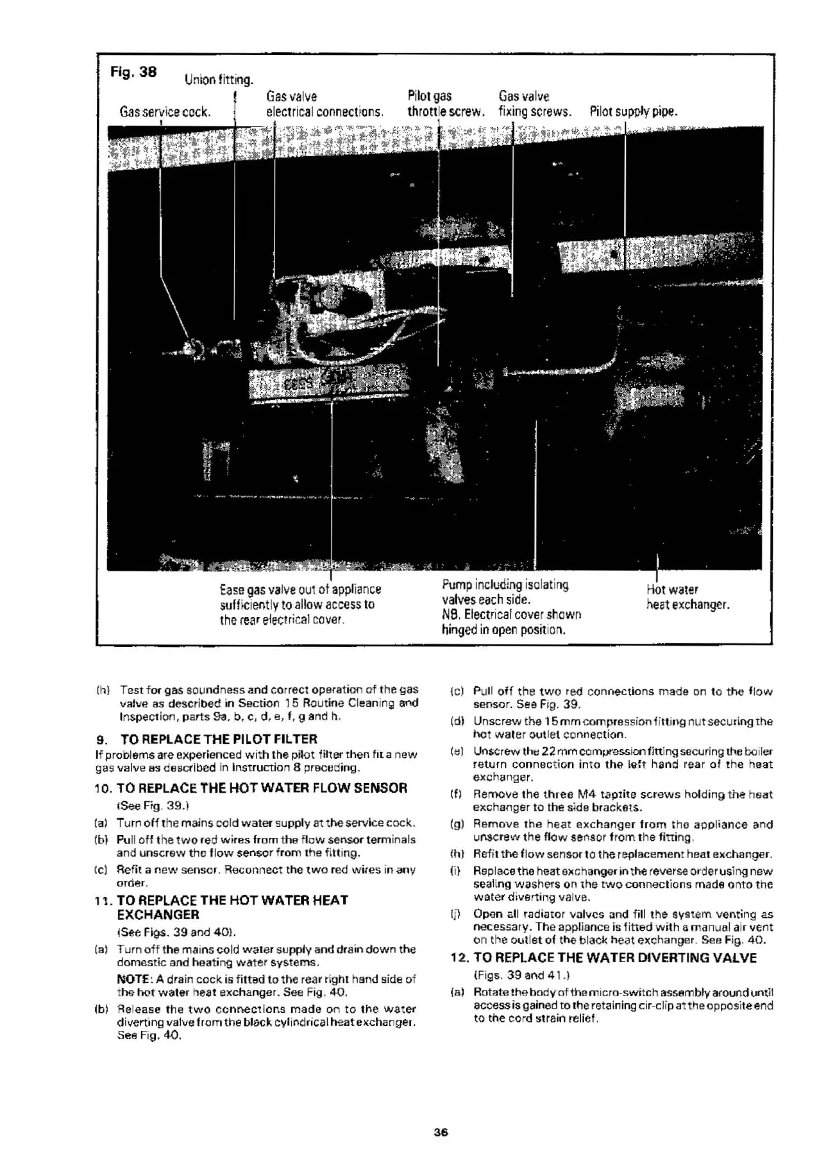
38
Union
fi
tt
i
ng.
Gas
va
l
ve
Pil
ot
gas
Gas val
ve
Ga
s se
rvice
cock
.
elec
t
ric
al
co
nn
ect
ions.
th
rottle s
crew.
fixing
sc
r
ews
. Pi
lo
t su
pp
ly p
ipe
.
tase
ga
s valve
out
of
app
l
iance
sufffci
ent
ly
to
al
l
ow
access
to
t
he
(ear electrical
co
ver
.
(h} Test f or
gas
soundness a
nd
correct
operat
i
on
of
the
gas
valve as described in
Sect
i
on
15
Ro
ut
i
ne
Cleaning and
Inspection, parts 9a, b, c, d, e, f, g and h.
9.
TO
REPLACE THE PILOT FILTER
If
prob
lems are experienced
wit
h the
pilot
filter then f
it
a
new
gas valve
as
descr
ibed in I
nst
ru
ction
8 preced
in
g.
10. TO REPLACE
THE
HOT
WATER
FLOW SENSOR
!See Fig.
39.)
[a)
Turn
off
the
mai
ns
cold
wate
r su
pp
ly
at
the service
cock.
(b)
Pu
ll
off
the
two
red
wires
from
the fl
ow
sensor terminals
and unsc
rew
the
fl
ow
se
n
sor
from
t
he
fi
tt
ing.
(C) Refit a
new
se
nsor
.
Reconnect
the
two
red wires in
any
order.
1
"1.
TO
REPLACE THE
HOT
WATER
HEAT
EXCHANGER
ISee Figs.
39
and 4
0)
.
(a)
Turn
off
the mains cold
wate
r supply and drain
down
the
d
om
estic
and heating
water
systems
.
NOTE
: A drain
cock
is f
it
te
d
to
the
rear
right
hand side
of
the
hot
wate
r heat e)(changer. See Fig .
40
.
(bl Release
the
two
co
n
nectio
ns
made
on
to
t
ne
water
dive
rting valve f
rom
the
bl
ack
cy
li
ndr
ical h
eat
exc
hanger.
Sea Fig.
40
.
P
um
p
in
cl
udin
g i
so
lati
ng
va
l
ves
each si
de.
H
ot
water
heat
exc
h
anger.
NB. E
lectrical
cover
sh
own
hing
ed
[n
op
en
posit
i
on.
36
{C)
Pull
off
the
tw
o red con
nect
i
ons
made
on to
the
f
low
sensor. See Fig.
39
.
(d) Unsc
rew
the
15
mm
co
mpre
ssion
ii
tt
i
ng
nut
securing
the
hot
wa
ter out let
connec
t
io
n.
(t:) Un
screw
the
2:2.
mm compression
fi
tt
ing securing the boiler
return
con
nectio
n
into
t
he
~ef
t
hand
rear
of
the h
eat
exchanger
.
(f) Remove
the
three
M4
taptite
sc
r
ews
ho
l
ding
the
h
eat
exchanger
to
the
side brackets.
(g)
Remove
the
heat
exc
hanger
fr
om
tho
appliance
and
unscrew the fl
ow
sensor f
rom
the
fi
tt
ing.
~h)
Refit
the
flow
sensor to the replacement heat exchanger.
(i)
Replace the heat
eJCc;
hanger
in
the rever
se
order using
new
sealing
wa
shers on the
two
c
on
nect
ions
ma
de
onto
the
wate
r d
iv
erting valve.
(j) Opon all radia
tor
vn
l
vcs
and fill
the
system
venting as
necessary.
The
appliance is 1itted
with
a
ma
nual air vent
on
the o
utlet
of the blacl< h
e<Jt
ex
changer. See F
ig
.
40.
12.
TO
REPLACE THE
WAT
ER DIVERTING
VA
l VE
(F
igs.
39
and
41
.)
{a)
Rotate
the
body
of
the
mi
cro-s
wi
tch assembly a(ound
unt
il
access is
ga
ined
to
the retaining
ei
r-e lip at
the
opposite and
to tne
cor
d strain reli
ef
.
 Loading...


