4.
SITING
THE
APPLIANCE
The appliance
may
be installed
in
any
room
a
lt
ho
ugh
pctrt
ic
ul
ar
attention
is
drawn
to
the requirements
of
the
I.E.E. Wi
ri
ng
Regulati
ons
and, in Scotland,
the
elec
tri
cal provisions of
the
Building Regulations applicable
in
Scotland .
With
respect
to
the
ins
tallation
of
the
appliance in a ro
om
containing a
bath
or
show
er. Where a ro
om
sealed appliance
is
i
nstalled
in
a room c
ont
aini
ng
a
bath
or
s
howe
r,
any
electr
ic
al
switch
or
appliance control
utilis
i
ng
mains ele
ct
ricity
should
be so
situa
ted that
it
c
annot
be
touched
by
a person us
ing
the
bath
or
s
hower.
!R6fer also
to
sections
2,
3, 6, 7 and S
.l
1. T
he
appliance is wa
ll
mou
n
ted,
no
special wall protection
is
reQ
uired.
If
the
buil
di
ng is
of
a timber frame
construc
tion
11-\e
guide
Hnes
and recommendati
of)S
laid d
ow
n
by
the
Brrtish Gas Corpo
ra
tion
sho
uld
be
fo
ll
owed
when mak!ng
the
balanced flue aperture.
2 . The w all to w
hic
h the appliance is to be fixed
mus
t be
capable
of
suppo
rting
its
we
igh1 (
referto
T
echnic~
l
Da
ta
Section 2). The wall mounti
ng
plate
together
w ith tl'le
fix
ing
tem
p!
ate, Fig . 4 should be used to enable the fixing
sc
r
ews
and
bal
anced
f
lue
cut out p
os
it i
on
to
be
determined.
3. T
he
follo
win
g clear
ances
mus
t be l
eft
to
all
ow
for
ins
tallation and servicir.g:·
In
sta
ll
at
io
n
Above
ln
front
Below
Side
150
mm
16
in.)
6DOmm
(:24
in.)
450
mm
(
18
in.)
See
no
te bel
ow
.
Ca
re
must
be giv
en
to ensure adequate space is available
ei
ther
side
for
mounting the appliance.
th
is
is
l
eft
to
the
discretion
of
the installer.
NOTE:
On
side flue applications a side cl
ea
rance
of
75
mm
(3 in.}
is
requi
re
d
to
fac
ih
t
ate
making good
in
ternal
waH
face
when
l
eft
or rig
ht
hand
ilue
out
let is selec
te
d.
Servicing a
nd
Operation
Above
50
mm
{2
in.)
In
front
600
mm
(24 in.)
Below
280m
m (1 1 i
n_
)
Ri
ght
and L
eft
Side
20
mm
(0_ 7 in.)
5.
SYSTEM
CONSIDERATIONS
1.
It
is
most
important that the f
low
ra
te sho
wn
in
Table 4
corresponding
to
the heating output that has b
een
selected
is achiev
ed
and a suitable by·pass
must
be
included as
describ
ed
in Section 9.
2. For circu
it
design purposes the pressure drop across the
appliance should be obtained
ft
om
Tab
le 4
us
i
ng
the
press
ur
e drop cortespondingtotheheatiflg ovtput chosen.
there is no need
to
take into account the higher boiler output
used for
domestic
hot
wate
r.
3.
When a dema
nd
is made
fo
r central heating the boiler
ou
tp
ut
is
modulated automatically from
8.8
kW
to
19
k W
(30-
64
.800
B
tu
/
h)
in or
der
to
give predominantly st
ab
le
ro
om
temperatu
res
.
4 _ When a demand is made
fo
r domestic
hotwa
ter theboiler
outpu
t
is
mod
ulated au
toma
ticallv
hom
8. 8
to
24
.0
kW
130-82,000
Btu/hi in order
to
give predominantly stable
ho
t
water
temperatures.
5. The unit heats
the domestic
hot
watet
instantaneously and
for the time that domestic
hot
wa
ter is being
dr
a
wn
off
the
central he
at
ing system is
temp
orarily i
nt
errupted. When
hot
wate
r
on
ly is selected
the
ur~
i
t
will
be
completely cold
and a
few
seco
nd
s w ill elapse while the heat exchangers
pre-h
eat
before hot
water
is o
bt
ained.
6.
Th
e appliance includes a cir
cu
l
at
i
ng
pump and
no
other is
required
7. Where room
an
d fr
os
t th
er
mostats
are
to
be used they
mus
t
be suitable
io
r mains application.
s
6.
AIR
SUPPLY
1. The room in
wh
ich
the
appliance is :nstalled does
not
require a purpose air
vent
-
2. l
fthc
appliance is installed in a cupboard or compatt
ment
.
permane
nt
air
vents
are required in
the
cupboard
or
compart
men
t,
one
at
high level. and one at l
ow
level,
eitherd
i
r4;!ct
to
outs
i
de
ai
r or to a room. Both high and l
ow
level air
ve
nt
s
must
comm
unicate w ith the same room or
mus
t both be on the same walt
toou
ts
ide air. The
mi
ni
mum
effect
ive ar
eas
requir
ed
are given !n Table
5.
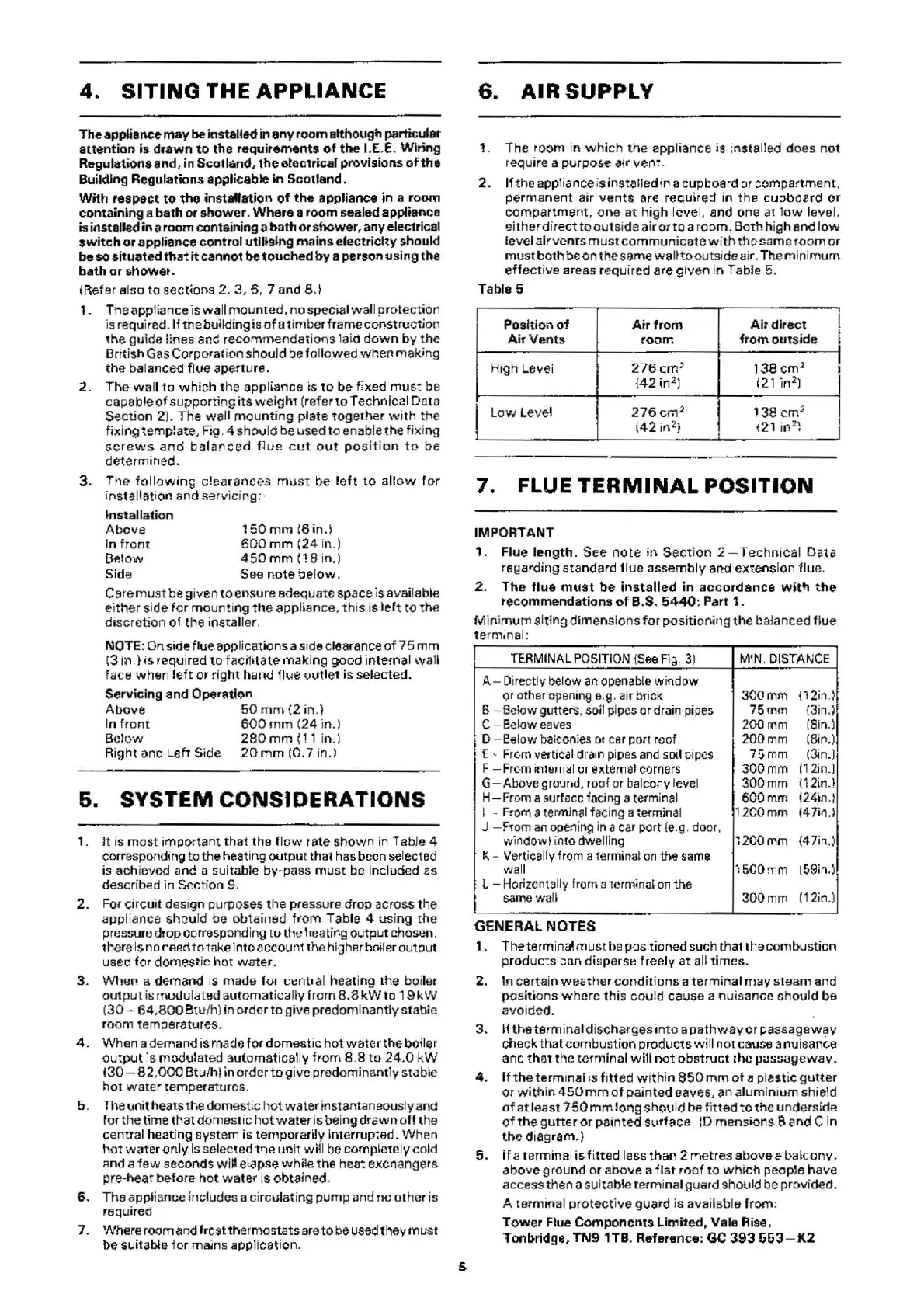
Table 5
Pos
iti
on
of
Air
fr
om
Ai
1 direct
I
Air
Vents
r
oom
fr
om
out
side
I
High Levei
27
6cm
}
1
38cm
2
I
{4
2 in
2
)
(21 in
2
l
j
I
L
ow
Level
276cm
2
138
cm
2
(
42
in
2
)
'
i2
1 in
2
\
7.
FLUE
TERMINAL
POSITION
IMPORTANT
1. Flue
length
. See
note
in
S
ection
2-Technical
Data
regarding
sta
ndard flue assembly and extensi
on
flue
.
2.
The
flue
mus
t
be
i
nstalle~
in ac c
ordance
wi
tt! the
rec
ommendation
s of B.S.
5440
: Part 1.
Minimum si
ting
dime
nsions
for
positioning
th
e balanced
flue
termjnal:
T
ER
MI
NAL
P
OS
ITI
ON
{
See
Fig.
3)
MIN.
DISTANCE
A-
Dire
ctly below
an
open
able
window
or oth
er
opening
e.g. air brick
300mm
!12in.)
I
l
B
-B
el
ow
gutters, soil pi
pes
or
drain pi
pes
75mm
(3in.)l
C
-
Be
low
eaves
200mm
(Sin.)
D-
Be
low
ba
lco
nies
ot c
ar
po
rt roof 2
00mm
(8i
l"'.
)
£ -
From
vertical d
ra1
n pip
es
and
so
il
pipes
75mm
(3in
.)
F
-From
inter
nal
or extern
al
comers
300mm
(12in.l
G-Above
ground, roof
or
ba
lcony level 300mm
!1
2in
.!
H-
From
a surfocc facing a termi
na
l 600mm
(24in.t
I
--
From
a term
ina
l facing a terminal 1200mm
147in
.)
J -
From
an
opening in a
car
po
rt
{e
.g. door,
w
in
dow~
in
to dwelling l
200mm
{47in.)
K- Vertically fr
om
a
te
rm
inat
on
t
he
sam&
wall
1500mm t59i
n.
l
L -
Horizont311y
from a 1ermina'
on
the
same
wall 3
00mm
(
12
in
_)
GENERAL
NOTES
1 . T
het
erminal
must
be
positioned such that the combustion
pr
oducts
c
an
d!~perse
freely
at
a
l~
times.
2.
In certain w eather
con
di
tions
a terminal
may
steam and
pos
iti
ons
where
th
is could ca:;se a nuisance
shou
ld be
avoided.
3.
H
the
term ina I di
sc
harges
into
a p
ethway
or passageway
check
tha
t combustion pr
oduc
ts
wi
ll
not cau
se
a nuisance
and
tha
t the ter
mi
nal
will
not
obst
r
uc
t t
he
pa
s
sageway.
4. If the terminal
is
fi
tt
ed
within
850
mm
of a plastic
gutte
r
or
with
in 4
50
mm
of
painted caves, an alumini
um
shield
of
at
least
750mmlong
should be f
it
ted
to
the
underside
of
the gu
tter
or
pai
nte
d
svr
face. m imensions a and c in
the d
iag
ra
m.)
5. if a terminal is f
it
t
ed
less
th
an
2 metres above a b
alcony
,
abo
ve
grou
nd
or above a
flat
ro
of
to
wh~ch
people have
a
cc
ess then a suitable termi
na
l guard should be
prov
ided.
A termi
na
l p
rotective
guard is available from:
Tower
Flue
Components
Limited
,
Vale
Rise,
Tonbridge,
TN9
1TB
. Reference: GC
393
55
3-
K2
 Loading...