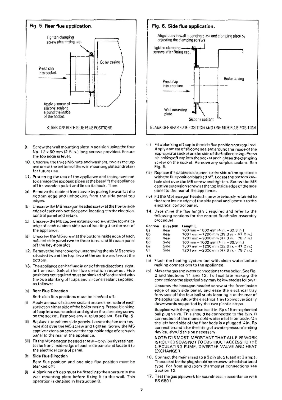
Fig. 5. Rear ftue application.
Trghten
clamp
il\g
screw
after fi
tt
i
ng
ca~
r
~
-
--
~
Press
cap
mto
socket.
! I
Ap~ya
M1earo
f
tl
_J
srll
c
one
sealant
around
the
ins
i
de
of
the
so
cke
t.
B'-A
i
..J
K
OFF
BOTH
S!
DE
FlUE
POSIT
i
ONS
9.
Screw
the
wall
mount
i
ng
pl
ate
in
posit
i
on
using the
four
No.
12
x
60
mm
t 2. 5 in.) long
screws
prov
ided. Ensure
the
top
ed
ge
is
level.
10
.
Unscrew
the
three M6
nu
ts
;~nd
washers
,
two
at
the
lOP
and one
at
the
bottom
of
the
wall
mounting plate and retain
for
•utur~
us
e.
11.
Protecting
the
r
eat
of
the
appliance and
tak
i
ng
care
not
to
damage
the
exposed pipes
at
the base
lift
the appliance
of
f its
wood
en
pallet
and lie
on
it
s b
ack
. Then:
Ia l Remove
th
El
cabi
net
fr
ont
c
over
by
pulling
forward
at
th
e
bo
ttom
edge
and
unhooki
r'l
g
from
the
side pan
el
top
edges.
(b
~
Unscrew
th
eM
5 hexagon headed
screw
at the front insi<ie
edge of each
cabinet
side panel
locating
ittothe
electrical
contr
ol panel and retain.
(c
t Unscrew the
M5
captive extensi
on
sc
rew
at the t
op
inside
edge
o1 each
cabinet
side panel
locating
it
to
the
rear
cf
th
e appliance.
(dl
Unscrew
theM
5screw
at
the
bottom
inside edge
of
each
cabi
net
si
de
panel
tw
o
to
t
hr
ee turns
and
l
ift
each panel
off
the
key-hole s
lot
.
12
. Remove
the
inner
cover
by
unscrewing the six M 5 s
cr
ews
si
tuat
ed
tw
o at
the
top
, t
wo
at
th
e
centro
i.ln
d
tw
o
at
the
bottom.
13
. The appliance can be flued
in
one
of
three directions. right,
lett
or
rear . Se
le
ct
t
he
flue
di
rec
t ion r
equired
. Flu e
positions
not
required
must
be
blanked
off
and
sealed
wi
th
the
two
blanking
of
f caps and sil
ico
ne sealant supplied.
as
f
ollows
:
(
o)
Rear Flue
Direction
Bot
h side fiue positions
must
be blar'lked
off:-
til Apply a smear
ot
sili
cof'e
seal
ant
around
the
in
side
of
each
socket on either side
oft
he
boile
r
ca
sing. Press a blanking
of
f cap
into
each
socket
and t
igh
ten t
he
clamping scr
ew
on
tt1e
socket. Remove
any
surp
lu
s sealant. See Fig. 5.
Iii) Replace the cabinet side panels. Locate
the
bottom
key
ho
le slot
over
the
M5
screw
ar1d
tigl"'1en.
Screw
the M 5
captive extension
screw
att
he
top
inside edge
of
each side
panel to
the
rear
oi
the a
pplian
ce.
(iii)
Fit
theM
5 h
exagon
headed scr
ew
-
previously
retained,
to
the
front
insi
de
edge
o1
each si
de
panel and
lo
cate
it
to
th
e elec
tr
ical
control
panel.
{b
~
Side Flue Direction
Rear flue
position
and o
ne
s
id
e flue position must be
blanked
off
:
lil
A blanki
ng
off
cap
must
be
fit
ted
in
to
the
aperture in the
wa
ll
mou
nti
ng
plate
before
fixing
it
10 1h
e
wall.
This
operation
is
detailed in I
nstr
u
ct
i
on
8.
7
Fig.
6.
Side flue application.
Align
hcles
i11
wail
rr.o
;,rntin
g
;>la
te
and
cla
mp
ir.g
plilt~
by
adjus
ti
ng
t
he
c
lamping
screws
Tight
en cl
amping--
-.J
screws
afte
r
fitting
ca
p.
I
BaUer
ca
sing
Pr1:1ss
cap
in
t
oilpe
rtur
e
-
-~-
!
f
I
Wail
mount
i
ng
\
--
-1
plate.
sm
cone
sealant
BLANK
OFF
REAR
F
LUE
POSiTION
ANO
ONE
SIDE
FLUE
POSITION
(;i ) F
it
o blanking
off
cap
in
t
hesid~
f1ue
position
not
reqtJired.
App
iy a smear
ot
sil
ic
one
seala
nt
around
the
insi
de
of
the
appropriate
socket
on
the
side
of
the
boi
l
er
casing. Press
a
blanking
off
ca
p i
nto
tk
e socket and 1ighten
tile
clamping
screw
on
the
socket
. R
emov
e
any
surplus sealant. Sec
Fig.
5.
{Hi
I Replace the cabine• side panel
to
tb~:
~ids
of the appliance
with
th
e flue position blanked o
ff
. Loca
te
tf'\e
bo
ttom
key-
hole
sl
ot
over
the
M5
screw
and
tighte
n.
Screw
the
M5
captive
extens
ion
screw
ilt the
top
inside edge
of
ttle
si
de
pane
l
to
the
reHr
of
the appliance.
li
vl
Fi
tthe
M5hexagon
!'leaded scr
ew
pre11iously retained
to
t
he
front
i
ns
ide edge
uf
tile
si
de
panel
and
lo
cate
it
to
the
electrical control panel.
14
. Determine
th
e flue
length
l required and
refer
to
the
follow
i
ng
secti
ons
for
the
co
rr
ect
flue/boiler assembly
procedure.
So
c
tion
Ba
Direct;
on
Rei!r
Rear
Rea
r
Side
length
l
lOO
mm
- 1
000
mrn i4 in.
-39
.9 in.)
1001
mm
-
1200
mm
(39.3
if'l
.
--
47.2 in.)
1201
mrn-4000mm
(
47
.
3i
n.
78
.7
in
.J
100
rnrn - l OOOmm !4 in.
-39
.3 i
n.)
1001
mm
-
1200
mm
(3.9.3
in
. -
-4
7 .2 in.)
1201
rnm-2000mm
147.3
in
. -
78.7
in,)
Sb
8c
8d
Be
81
15
.
Si
cle
Si
de
(a
't Flush the heating
system
o
ut
wilh
clean
wate
r
before
mak
ing
connections
to
the
appliance.
lb
I
Mak
e the
~as
and
water
connections
to
th
e boiler. See Fig.
2
an
d
Sect
i
ons
11
and
12
.
To
f!icil
it ate
maki
ng
the
connections the electricat tray may be lowered
as
fo!lovv
~:
Unscrew
the
hexa
gon
headed
screw
at
the
front
inside
edge
of
each si
de
panel, and
e
a
s~
t
he
elec
trical
tray
f
orwar
ds
off
the
four
ball studs
locating
it
to
the
rear
of
the
applian
ce
.
Alluw
'h
e electrical
tray
to
pivot
vertLCelly
downwards
supported
by
th
e
tw
o
plast
ic
stops
.
Suppbed w
it
h the appliance is a
'1:!
in.
Rp
x 1 5
mm
sph~
ri
c;~
l
ball
plug
valve. This
sho
uld
be
connected
to
rhe
Y2
in
. R
co
nn
ect ion o f
the
mains cold
water
in
l
et
filter
body
..
On
the
left
hand side
of
the
fil
te
r
bo
dy
is
a plugged
'A
in
. Rp
connection and is
for
th
e fitting
of
a
wa
ter pressure limi
ting
devi
ce, s
ho
u
ld
this
be
necessary. •
NOTE: IT IS
MOST
IMPORT
ANT
THAT
ALL
PIPE
WORK
IS R
OU
TED SO
AS
NOT
TO OBSTRUCT
AC
CESS
TO
THE
CIRCULATING PUM
P,
DIVERTER
VALVE
AND
HEAT
EXCHANGER
.
16
. Connect the ma
ins
lead
to
a 3 pin pl
ug
fused at 3
amps
.
The socket for the plug shou
ld
be
an
un
s
wit
ched shuttered
typ
e. For
frost
and room
thermo
s
tet
con
n
ections
s
ee
Sec
ti
on
12
.
17
. Te
st
th
e gas
pi
pewo
rk
for
soundness in
coc
c
or
dance
wit
h
BS
6891
.
 Loading...


