B
B
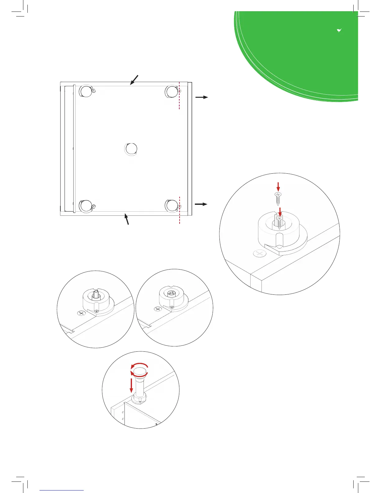
Step 11.
Secure each of the legs into place with 2 x 15mm screws (L) per leg
Step 13.
Push leg rmly down into leg base.
Adjust legs to 155mm before turning carcass
upright. Once in situ level accordingly.
Step 12.
Lightly hit centre peg of leg base with hammer
until ush with the leg base.
Ensure legs are rotated as shown so that part
of it is supporting the end panels (B).
Front legs should have at edge to the front.
Front
Front
Leg position diagram
C
C
C
B
L
L
C
B
B
C
B