-
7
-
10.3.3. Workplace Requirement
Fig 9 shows the minimum distance (cm) from walls after assembly this auxiliary device. Please choose the
right place to install it.
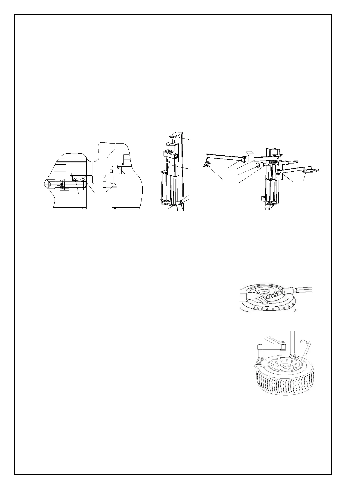
10.3.4.Assembly
1) Disconnect the tire changer from power supply and air source.
2) Install the column 3 with screw 1 and 2; install the support 5 of the auxiliary arm with screw 4; (Fig 10)
3) Install the help arm 6 with nut 7 and screw 9,then tighen 4、7、8、9(Fig 10 、Fig 11);
4) Install the Rotating arm (A)、Hexegona
l horizontal arm (B) and Tire lifting roller support (C) separately on the
tire changer;(Fig 12)
5) Install the tire lifting roller (D)、 the switch (E)、tire pressing head (F) and tire pressing roller(G) separately on
the tire changer;(Fig 12)
6) Connect the air hose to the corresponding joint through the rear hole of the body.
10.4. Functional Parts
Fig 12 shows functional parts to the 036 device:
A. Rotating arm connector B. Hexagonal horizontal arm
C. Tire lifting roller s
upport D. Tire lifting roller
E. Raise-fall control assembly
G. Tire pressing roller
10.5. Trial operation
The 036 device must connect with the air compressor, and the air pressure from 8 bars to
10 bars is desirable.
10.6. Operations
Mounting and demounting big flat tire is difficult work. By the help of 036 help arm to
mount/demount the tire from the tire bead will make the operation easier. It is a good
helper for tire changer.
10.6.1. Fixing The Tire
Loosen the bead according to the manual. Clamp the tire from outside, tread the corresponding
7
1
2
3
4
5
A
B
G
E
F
C D
 Loading...