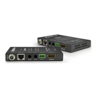
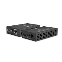
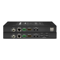
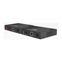
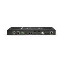
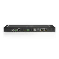
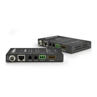
Front Panel (TX/RX) Rear Panel (TX/RX)
Power LED
Solid: The receiver is powered On
Off: The receiver is powered Off
Status LED
Flashing: The receiver is operating normally.
Off: The receiver is Not operating normally.
HDCP LED
Solid: HDCP content is present.
Flashing: HDCP content is not present.
Off: No signal.
LINK LED
Solid: Link to receiver has been established.
Flashing: Link to receiver has not been
established.
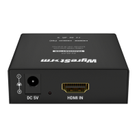
Power In
5.5mm Screw Down Barrel Jack
Connect to the included 18V DC 1A power
supply to the transmitter. A power supply
is not required on the receiver as it will be
powered using PoH. See Power Supply Wiring
for important information.
HDBT Out (TX)
HDBT In (RX)
8-pin RJ-45 female | 10/100 Mbps auto-
negotiating
Connect the transmitter HDBT Out to receiver
HDBT In using the cable created in Pre Wire
step 1.
IR TX/RX
IR TX - 3.5mm (1/8in) Mono Jack - Connect
to the supplied IR emitter to control a local
device from the remote display location via
HDBaseT.
IR RX - 3.5mm (1/8in) Stereo Jack - Connect
to the supplied IR receiver to send IR to the
remote display via HDBaseT.
See IR Wiring for more information.
HDMI In (TX)
HDMI Out (RX)
19-pin type A HDMI female
Supports HDMI and DVI/D (requires adapter -
not included).
Copyright © 2017 WyreStorm Technologies | wyrestorm.com
EX-70-G2 Quickstart Guide | 170724
North America: 518-289-1294 | EMEA/ROW: 44 (0) 1793 230 343
support@wyrestorm.com
2 of 4
EX-70-G2 Transmitter
EX-70-G2 Receiver
A B C D
EX-70-G2 Transmitter
EX-70-G2 Receiver
A B C D
 Loading...