Basic Installation Procedures
975-0787-01-01 33
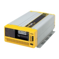
the Neutral (N), Ground(G), and Line (L) connections.
9.
Tighten the strain relief clamp to secure the wires.
10.
Replace the wiring compartment cover (using a #2 Phillips
torque screwdriver - see WARNING), if you are finished with
connecting all the AC wires in the unit (and installing the
GFCI).
WARNING
ELECTRICAL SHOCK HAZARD
Use a torque screwdriver to tighten the captive nut panel screw to
5in-lb torque of force to ensure a proper ground connection and a
required tool access to the wiring compartment.
Failure to follow these instructions can result in death, serious
injury, or equipment damage.
11. Connect the other end of the wires to a circuit breaker in the
inverter distribution panel.
Step 6: Connecting the DC Cables
NOTICE
REVERSE POLARITY
l
Check cable polarity at both the battery and the Freedom X
before making the final DC connection. Positive must be
connected to positive; negative must be connected to
negative. Check to see if the reverse polarity LED (see Step
6: Connecting the DC Cables) is not illuminated.
l
Reversing the positive and negative battery cables will blow
a fuse in the Freedom X and void your warranty.
Failure to follow these instructions can result in equipment
damage.
WARNING
FIRE HAZARD
Use only copper wire rated 75 °C minimum. Make sure all DC
connections are tight to a torque of 71–80 in-lb (8–9Nm) of force.
Loose connections will overheat.
Failure to follow these instructions can result in death, serious
injury, or equipment damage.
Follow the procedure given below to connect the battery leads to
the terminals on the DC end. The cables should be as short as

 Loading...