Do you have a question about the Xantrex Freedom HF and is the answer not in the manual?
Details critical safety instructions to prevent electrical shock, including warnings about water and disassembly.
Provides safety guidelines to prevent fire and burns, focusing on ventilation and avoiding certain charger types.
Outlines precautions regarding battery handling and installation in potentially hazardous environments to prevent explosions.
Warns about hazards from short-circuit current, fire, and explosion from vented battery gases, requiring protective gear.
Emphasizes ventilation and careful handling of battery chemicals and gases during charging preparation.
Warns against installing the inverter/charger in engine compartments due to fire risk.
Describes the power output capabilities and suitability for various appliances.
Explains how the unit provides independent power during shore power interruptions.
Highlights built-in protection features for batteries and equipment, including low battery alarm and three-stage charging.
Details how the unit alerts and shuts down during overload or overheating conditions.
Describes the user-selectable low battery shutdown voltage thresholds.
Details the three-stage charging system that optimizes battery life and performance.
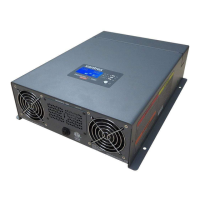
Covers the display panel, remote panel, buttons, and ports for monitoring and control.
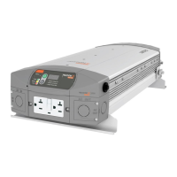
Covers GFCI receptacles, WAGO terminals, and PTI connectors for AC output and input.
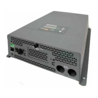
Describes the terminals for connecting the negative and positive DC cables to the battery.
Details the three-color LED indicating the mode of operation.
Explains the button used to change displayed status information.
Covers configuration, setting battery types, and adjusting feature settings.
Covers operation in shore power, inverter modes, and power transitions.
Covers operating limits, inverter loads, and overload operation.
Covers battery charging procedures and routine maintenance guidelines.
Details how to configure the unit for different lead-acid battery types using dip switches.
Explains the function of the Inverter Power button for operation and settings.
Describes the LED display for showing status information and fault codes.
Warns against disassembling the unit due to shock and burn risks.
Reiterates the danger of disassembling the unit and potential injury.
| Output Voltage | 120 VAC |
|---|---|
| Output Frequency | 60 Hz |
| Input Voltage | 12 VDC |
| Waveform | Modified Sine Wave |
| Surge Power | 3600W |
| Operating Temperature | 0°C to 40°C |
| Efficiency | 90% |
| Protection Features | Overload, Over temperature, Short circuit |