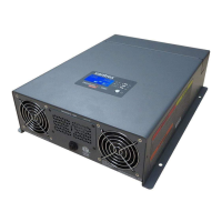
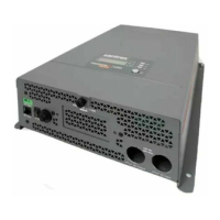
Side Panel
22 Freedom HF Owner's Guide
Side Panel
Figure 11 Side Panel
Item Description
1 15 A supplementary protector provides overload protection for
the GFCI receptacles. In a hard wired installation, the supplementary
protector doesnot protect output wiring. However, for models
Freedom HF 1055 (PNs: 806-1054, 806-1054-01), Freedom HF
1500 (PN: 806-1544), and Freedom HF 1800 T (PN: 806-1840-01,
806-1840-03, 806-1840-04), the hard-wired AC output connector is
protected by both the 15 A supplementaryprotector and the GFCI.
2 Grounding stud provides a ground path for the Freedom HF
chassis to the DC system ground.
3 Main cooling fan turnson when powering loads above 500 watts
or when the internal temperature reaches a set point temperature.
4 Auxiliary cooling fan (1800-watt modelsonly) performs the same
function as the main cooling fan.
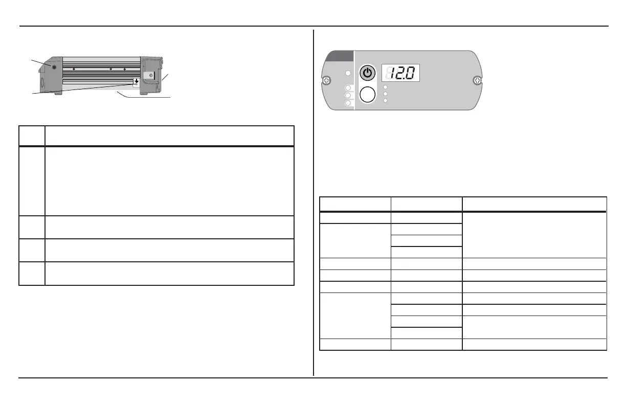
Remote Display Panel
FREEDOM HF
Input Voltage(V)
Select
STATUS
Battery
Fault
Ut ility
Input Current (A)
Output Power (kW)
Figure 12 Remote Display Panel
NOTE: Not all Freedom HF remote display panels are compatible
with different Freedom HF inverter/chargers. Please refer to the
compatibility chart below (when ordering an optional or a
replacement) to confirm which remote display panel is compatible
with your Freedom HF unit.
Model PN Remote Display Panel PN
Freedom HF 1000 806-1020
808-1840
Freedom HF 1055 806-1054
806-1054-01
806-1055
Freedom HF 1055 EMS 806-1055-02 808-1840
Freedom HF 1500 806-1544, 806-1544-01 808-1544
Freedom HF 1800 806-1840 808-1840
Freedom HF 1800 T 806-1840-01 808-1840-01
806-1840-04 808-1840-04
806-1840-03
808-1840-03
806-1840-05
Freedom HF 1800 EMS 806-1840-02 808-1840

 Loading...