Load Connection and Sensing
Load Connection
Release 2.2 29
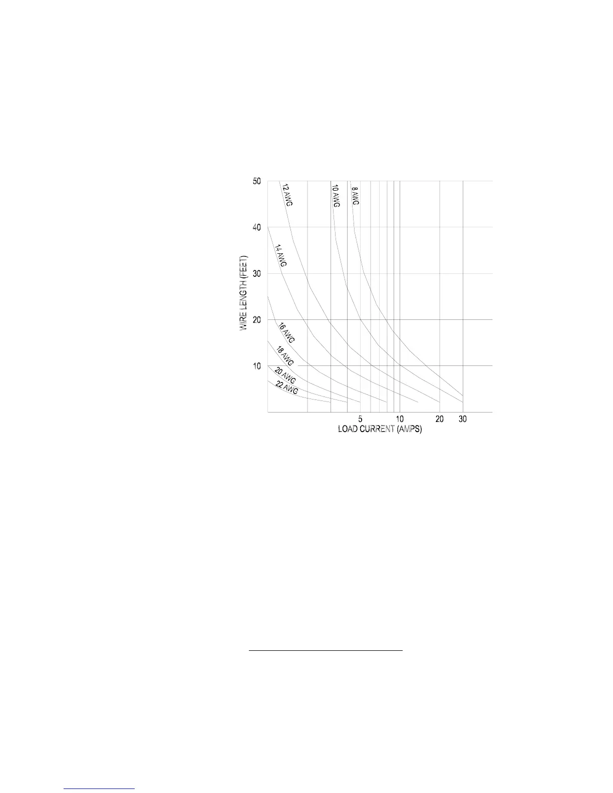
Load Wiring Length for Operation with Sense Lines For applications using
remote sensing, you must limit the voltage drop across each load line. See Figure 3.1
for some maximum allowable lengths for a given load current and wire size. We
recommend that you use the larger load wiring to ensure a smaller voltage drop
(0.1 V typical maximum), although units can compensate for up to 0.5 V drop in
each line
1
.)
Figure 3.1 Maximum Wire Length for 100 mV Line Drop
Noise and Impedance Effects To minimize noise pickup or radiation, use
shielded pair wiring of the shortest possible length for load wires. Connect the shield
to the chassis via the front panel binding post or a rear panel mounting screw. Where
shielding is impossible or impractical, simply twisting the wires together will offer
some noise immunity.
Making Load
Connections
Front Panel Binding Posts To make connections at the front panel, connect
load wires using stripped wire (0.6"), tongue lugs, or banana plugs to the output
binding posts.
For binding posts locations, see Figure 1.1 Front Panel Controls, p. 13.
1. Any losses in the load cables must be deducted from the maximum output voltage of
the supply. For example, a 15 V supply with a 1 V loss in the load cables can supply a
maximum of 14 V regulated at the load.
 Loading...