Features and Specifications
Front Panel Controls
Release 2.2 13
Front Panel Controls
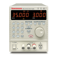
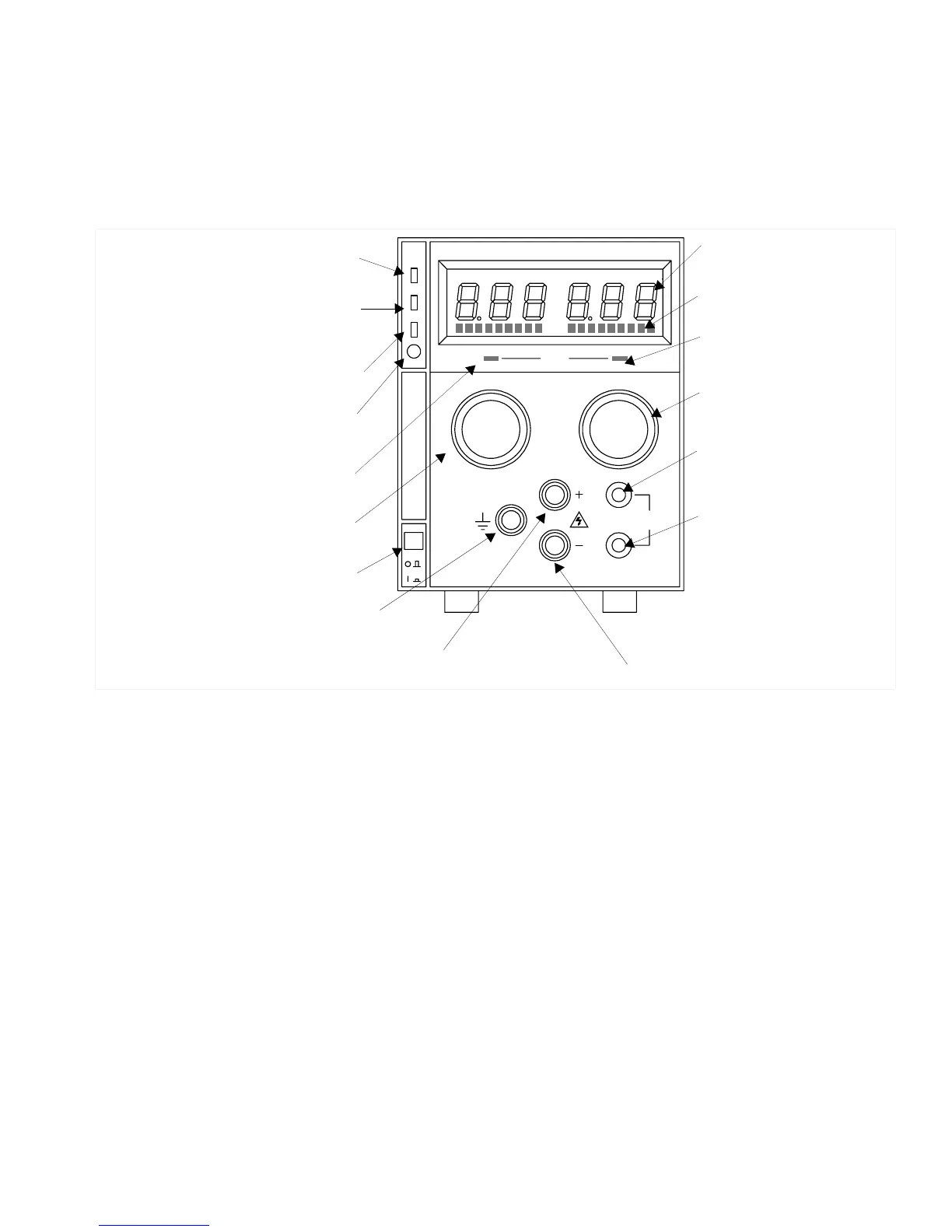
See Figure 1.1 to review the controls, LEDs, and meters located on the unit’s front
panel.
Figure 1.1 Front Panel Controls
REGULATED DC POWER SUPPLY
MODE
VOLTAGE CURRENT
SENSE
POWER
P
G
S
/
D
O
V
P
OVP
ADJ
M
Shutdown LED (S/D)
(For units with APG installed.)
Voltage Mode
Indicator (Green LED)
Safety Ground
Binding Post (Green)
AC Power Switch
Positive (+) Output Binding Post (Red)
Voltage Control Knob
(10-turn standard)
OVP Shutdown (OVP)
(For units with APG installed.)
OVP Adjust Potentiometer (OVP ADJ)
(For units with APG installed.)
Digital Display of DC Output
(Volts, Amperes)
Analog Bar Graph Display
Current Limit Mode
Indicator (Red LED)
Current Limit Adjust Knob
(1-turn standard)
Positive (+) Sense
Connection (Banana Jack)
Return (−) Sense
Connection (Banana Jack)
Return (−) Output Binding
Post (Black)
Remote Programming LED (PGM)
(For units with APG installed.
See also Figure 1.2).
 Loading...