Alto Hardware Manual Section
6:
Disk and Controller
47
Then
a sync word
is
written
(if
writing)
or
awaited
(if
reading). Finally
the
main transfer loop is entered.
Here the word count
is
decremented, a memory operation
is
started,
and
control is dispatched
on
the
transfer type.
If
read, the disk word
is
stored in memory.
If
write, the memory word is sent to the disk.
If
check, the memory word is compared with
O.
If
non-zero, the disk
and
memory words are compared.
An unequal compare here terminates this sector's operation
'with an
error
immediately.
If
the memory
word is
0,
it is replaced by
the
disk word.
In
any case, the checksum is updated
and
control returns to
the
main
transfer loop.
Due
to the
ALU
functions available, the main transfer loop moves in sequence
from high
to low main memory addresses.
After. the word count reaches
0,
the checksum
is
written
or
checked. A checksum error will
be
noted
in
the status word,
but
will not terminate this sector's operation. A finishing delay is computed, based
on
the current operation, the disk unit
is
set into a delay
mode
appropriate
to
the operation,
and
the delay
happens. Finally, all disk transfers are shut off, the record number
is
incremented,
and
control returns to
the beginning
of
the word task.
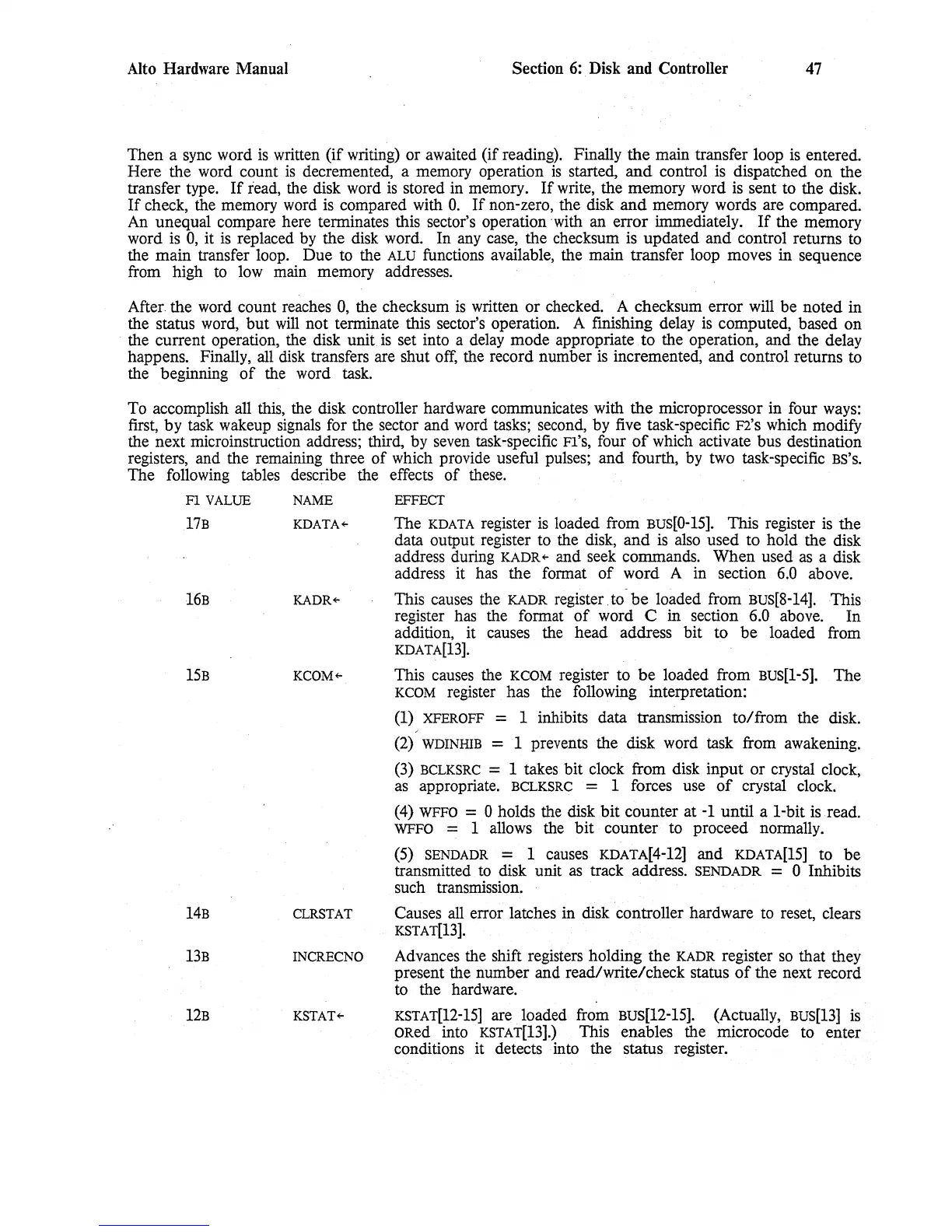
To accomplish all this, the disk controller hardware communicates with
the
microprocessor in four ways:
first,
by
task wakeup signals for the sector and word tasks; second, by five task-specific F2'S which modify
the next microinstruction address;
third, by seven task-specific Fl'S, four
of
which activate bus destination
registers, and the remaining three
of
which provide useful pulses;
and
fourth, by two task-specific
BS'S.
The
following tables describe the effects
of
these.
Fl
VALUE
17B
16B
15B
14B
13B
12B
NAME
KDATA~
KADR~
KCOM+-
CLRSTAT
INCRECNO
KSTAT~
EFFECT
The
KDATA
register is loaded from Bus[0-15]. This register is
the
data output register to the disk,
and
is also
used
to
hold the disk
address during
KADR+-
and seek commands.
When
used as a disk
address it has
the
format
of
word
A in section
6.0
above.
This causes the
KADR
register to
be
loaded from
BuS[8-14].This
register has the format
of
word C in section 6.0 above.
In
addition, it causes the head address bit
to
be
loaded from
KDATA[13].
This causes the
KCOM
register to
be
loaded from
BUS[1-5].
The
KCOM
register has the following interpretation:
(1)
XFEROFF
= 1 inhibits data transmission
to/from
the disk.
,
(2)
WDINHIB
=
'1
prevents the disk word task from awakening.
(3)
BCLKSRC
= 1 takes
bit
clock from disk
input
or
crystal clock,
as appropriate.
BCLKSRC
= 1 forces use
of
crystal clock.
(4)
WFFO
= 0 holds the disk
bit
counter
at
-1
until
a
I-bit
is read.
WFFO
= 1 allows the
bit
counter
to proceed normally.
(5)
SENDADR
= I causes
KDATA[4-12]
and
KDATA[15]
to
be
transmitted to disk unit as track address.
SENDADR
= 0 Inhibits
such transmission.
Causes all error latches in disk controller hardware to reset, clears
KSTAT[13].
Advances the shift registers holding the
KADR
register so that they
present the number and read/write/check status
of
the next record
to the hardware.
KSTAT[12-I5]
are loaded from Bus[12-I5]. (Actually,
BUS[13]
is
ORed
into'
KSTAT[13].)
This enables the microcode to enter
conditions it detects into the status register.
 Loading...