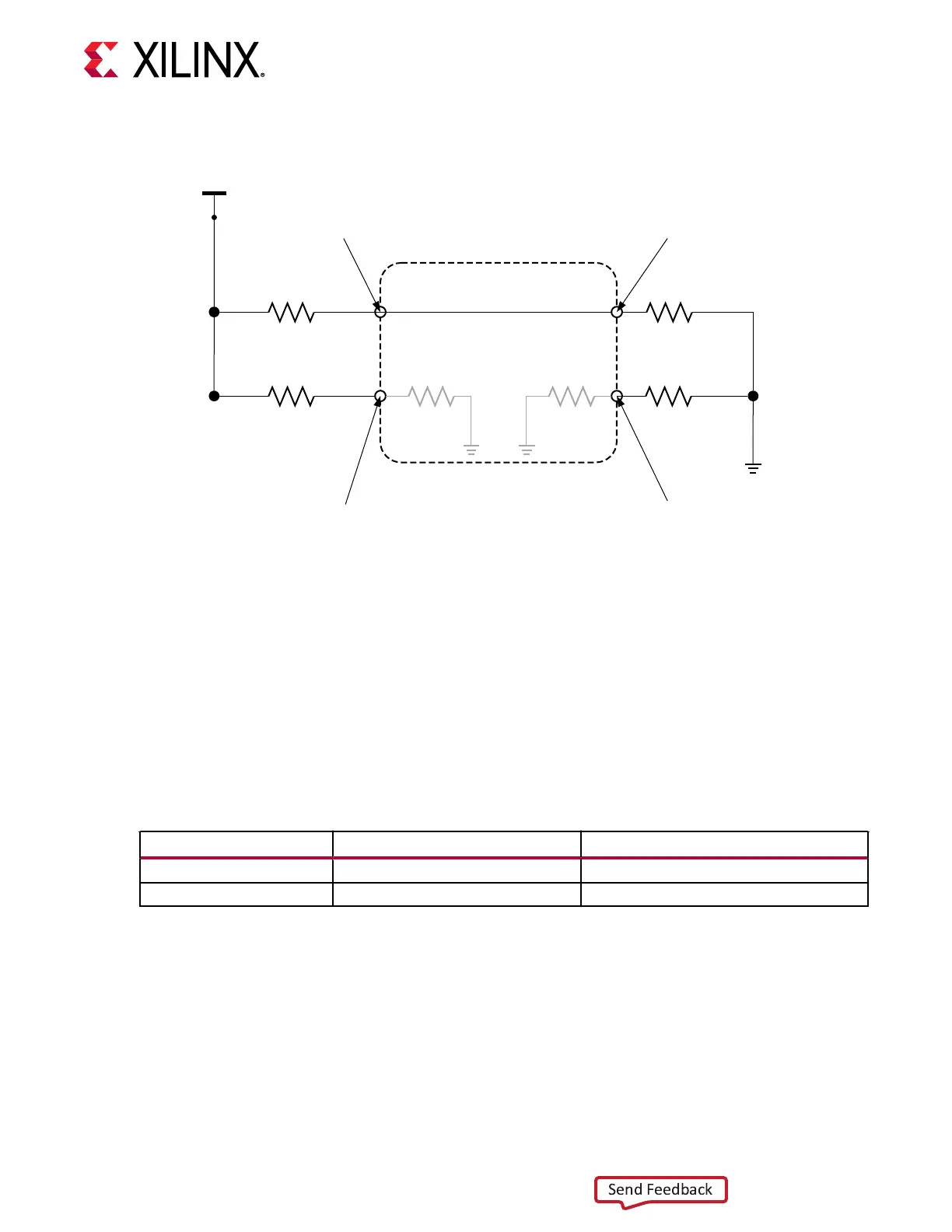
Figure 15: CC Connections
Rp
Rp
Ra Ra Rd
Rd
CC
Cable
5V
Source
monitors for
connection
Source
monitors for
connection
Sink
monitors for
orientation
Sink
monitors for
orientation
X25133-022221
The CC lines should be connected as follows in order to have the host detect the device as a USB
2.0 peripheral. The SmartLynq+ Module supports USB-C in a single orientaon currently for
HSDP capability. The following LED status can be used to check if the USB-C cable is connected
in the expected orientaon:
• Green: USB-C is properly connected
• Amber: Either the cable is not connected or needs to be ipped
○ Pressing the "SL+" tab select key on the display shows the root cause for the amber LED.
Table 9: CC Connections
HSDP Name Connection Desciption
CC1 Rd = 5.1 KΩ The UFP Rd value is fixed at 5.1 kΩ.
CC2 Rd = 5.1 KΩ The UFP Rd value is fixed at 5.1 kΩ.
Versal ACAP Connectivity
• See the VCK190 Schemacs (XTP610) for a sample board connecvity.
• For the HSDP connector, follow the recommended USBC guidelines to run at 10 Gb/s. The
preceding table contains some of the highlights of these requirements.
• When connecng the GTs from the Versal ACAP to the HSDP connector, keep the dierenal
lengths matched and close to the connector.
Chapter 9: HSDP Target Interface
UG1514 (v1.0) March 8, 2021 www.xilinx.com
SmartLynq Module+ 33