Do you have a question about the Xinje DS2-20P7-AS and is the answer not in the manual?
Safety checks for delivered products to prevent electric shock.
Precautions during installation to avoid electric shock and fire.
Safety measures for wiring to prevent electric shock and fire.
Safety guidelines during operation to prevent injury and electric shock.
Overview of the manual's structure and content chapters.
Identifies the target audience for this manual.
Information on obtaining the manual.
Checklist for verifying delivered products and their condition.
Explains product identification and naming conventions.
Table showing compatible servo drives and motors.
Installation guidelines for servomotors.
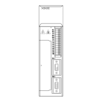
Installation guidelines for servo drives.
Guidelines for servo drive installation orientation.
Procedures for installing servo drives.
Instructions for wiring the main circuits of the servo drive.
Details of main circuit terminal connections.
Explains winding terminals on the servo motor.
Description of CNO, CN1, and CN2 terminal connections.
Information on communication port connections.
Overview of signal terminals.
Details of pulse signal connections.
Configuration for SI input signals.
Explanation of analog input circuits.
Details of output signal configurations.
Information on encoder feedback signals.
Provides a standard wiring example.
Example wiring for position control mode.
Explanation and connection of regenerative resistors.
Introduction to basic operation of the operate panel.
Describes the functions of the operate panel buttons and LEDs.
How to switch between different operating modes.
Explains different running status modes and codes.
Details on how to use the monitoring mode.
Guide to using auxiliary functions.
System information display functions.
Auxiliary run modes and results.
Procedure to set the motor type.
How to check alarm codes and related data.
Procedure to reset parameters to default values.
Using external monitoring mode.
How alarms are displayed and reset.
Example of parameter adjustment.
Explains how to select control modes.
Overview of basic function settings.
How to enable servo ON.
Changing motor rotation direction.
Setting motor stop modes based on overtravel signals.
Configuring overtravel limits.
Function and wiring of the power-off brake.
How to configure alarm output signals.
Recording and clearing servo running time.
Setting limits for torque.
Details on position control using external pulse commands.
Selecting control modes for pulse command.
Explains different pulse command modes.
Setting up the electronic gear ratio.
Filtering position command pulses.
Clearing pulse deviations.
Signal for confirming positioning completion.
Signal indicating near proximity to target position.
Prohibiting command pulses.
Position control using internal commands.
Selecting control modes for internal position.
Details of internal position mode settings.
Parameters for multi-segment position control.
Signal for changing position control steps.
Pausing current position control stage.
Skipping current position control stage.
Procedures for finding the reference origin.
Speed control using analog voltage command.
Selecting control modes for analog speed control.
Setting the analog voltage for rated speed.
Auto-adjusting speed command offset.
Using proportion action command.
Function and setting of zero clamp.
Checking speed coincidence.
Overview of torque limiting functions.
Setting internal torque limits.
Setting external torque limits via input signal.
Setting external torque limits via analog voltage.
Setting external torque limits using multiple inputs.
Signal for output torque reaching limit value.
Configuration of soft start acceleration/deceleration.
Setting speed command and feedback filters.
Setting dead voltage for speed command input.
Speed control using internal speed settings.
Selecting control modes for internal speed control.
Setting internal speeds 1, 2, and 3.
Configuring input signals for speed switching.
Speed control using pulse frequency commands.
Selecting control modes for pulse frequency speed control.
Details on pulse frequency command.
Setting command pulse frequency at rated speed.
Setting filter time for speed command pulses.
Torque control using analog voltage command.
Selecting control modes for analog torque control.
Setting analog voltage for rated torque.
Auto-adjusting torque command offset.
Setting filter time for torque command.
Overview of torque limiting functions.
Setting internal speed limits in torque control.
Setting external speed limits.
Signal for outputting speed up to limit value.
Setting dead area voltage for torque command.
Torque control using internal settings.
Selecting control modes for internal torque control.
Setting internal torque command values.
Switching control modes via external signals.
Overview of other output signals.
Servo alarm and reset signals.
Warning output signal.
Signal for rotation checking.
Signal indicating servo readiness.
Encoder Z phase signal output.
AB phase feedback signal for encoders.
Overview of I/O signal distribution.
How input signals are distributed.
Default configurations for input terminals.
How output signals are distributed.
Default configurations for output terminals.
Adjusting gain parameters for the speed loop.
Adjusting gain parameters for the position loop.
Practical advice for parameter adjustment.
Input signal for P/PI control of speed loop.
Switching gain online using an external signal.
General information about servo motors.
Detailed specifications of servo motors.
Torque-speed characteristic curves for servo motors.
Dimensional drawings of servo motors.
General information about servo drives.
General specifications of servo drives.
Detailed performance specifications of servo drives.
Application example for pulse command position mode.
| Brand | Xinje |
|---|---|
| Model | DS2-20P7-AS |
| Category | Servo Drives |
| Language | English |