72
It is recommended that the filtering time be 1/6 of the input pulse period and not more than 1/2 of the
input pulse period.
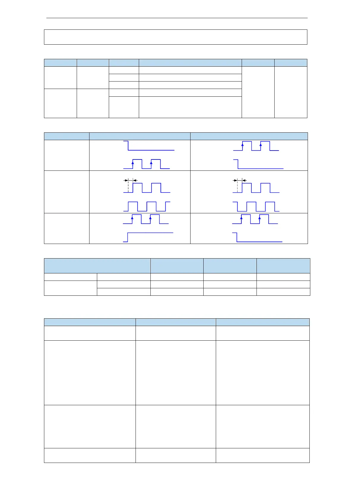
3. set the pulse instruction form
Pulse + direction (defaulted)
Effective
edge of
pulse
signal
4. Logical form of instruction pulse
5. Pulse specification
5.3.3 Position control (Internal command)
P0-01 control mode selection
Set to 5: internal position
mode
P4-03 internal position mode
P4-04 valid segment number
P4-10~P4-254 internal position 1
to 35 parameters
Control mode setting of
internal position mode:
including step change mode,
positioning mode and
adjustment time
Configuration of pulse
displacement, speed,
acceleration and deceleration
time of each segment
P5-35 change step
signal/GHGSTP
P5-32 pause present segment
signal /INHIBIT
P5-31 jump present segment
signal /Z-CLAMP
Common terminal function
assignment
P4-00 number of Z-phase signal
after leaving limit switch
Internal position back to
origin setting parameters
 Loading...
