XO
®
4 User Guide YB-253 Version 3.10
21
10 Symbols and glossary
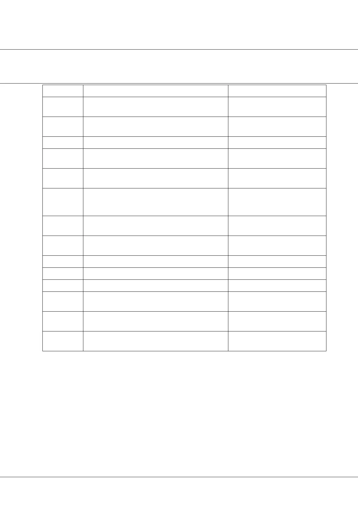
Text / Symbol Definition See section
Selected unit
instrument
The first instrument which is lifted forward 3.2.1
Active unit in-
strument
A selected unit instrument is activated by XO Foot Control 3.2.1
XO Joystick A joystick on the unit/chair base 3.1.3
XO Chip Blow Compressed air with high pressure being emitted from the in-
strument spray tubes
See XO 4 Configuration Guide
Configuration
switch
A switch under the instrument table used for configuring XO 4 See XO 4 Configuration Guide
Factory default
configuration
(of unit)
The configuration of the unit when supplied from the factory See XO 4 Configuration Guide
XO Foot Con-
trol
The XO Foot Control is placed on the floor and consists of a pe-
dal and a joystick as well as 2 switches (only XO 4-2 and XO 4-6)
3.1.3
Joystick on XO
Foot Control
The joystick on XO Foot Control 3.3.1
Last Position The chair position prior to the present position 3.3.1
Pedal The pedal of XO Foot Control 3.2.1
Rinse Position Chair position, which gives the patient optimal access to rinse 3.3.1
Spray selecti-
on
Combination (not amount) of spray water and spray air See XO 4 Quick Guide
Unit configura-
tion
The basic configuration of the unit See XO 4 Configuration Guide
Zero Position
of chair
Chair position where the patient enters/exits the chair 3.3.1
Table 7: Symbols and glossary