This document outlines the installation and basic usage of the XOMAX XM-CDB623 and XM-CDB624 multimedia units, providing essential safety instructions, connection diagrams, and troubleshooting tips. It serves as a generalized guide, acknowledging that some details or depictions may vary slightly between specific product models. For a comprehensive understanding, users are encouraged to download the detailed manual from the XOMAX website.
Function Description
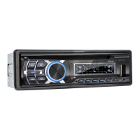
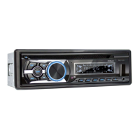
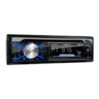
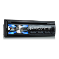
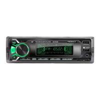
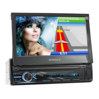
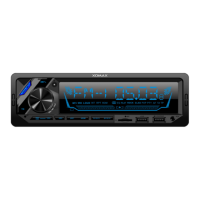
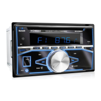
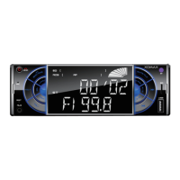
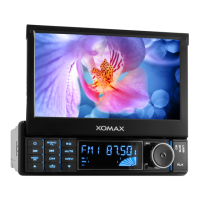
The XOMAX XM-CDB623 and XM-CDB624 are multimedia units designed for in-vehicle entertainment and information. They are intended to be integrated into a vehicle's dashboard, providing audio playback, radio reception, and potentially other multimedia functionalities. The units are designed to operate with a 12-volt on-board power supply and support connection to up to four speakers. The installation process involves securing the unit within the vehicle's radio slot, connecting the necessary power and speaker cables via ISO plugs and Cinch multicore connectors, and attaching the radio aerial.
Usage Features
- Installation: The manual provides a step-by-step guide for installing the unit, including preparing instruments, fixing the fixation sheet (if applicable), securing the installation frame, connecting the unit's cables, and finally fixing the unit itself. It emphasizes the importance of proper grounding and correct cable connections to prevent malfunctions or damage.
- Deinstallation: Instructions for safely removing the unit are also provided, detailing how to unloose the fixation nut, use extraction keys to release the unit from the frame, and disconnect all cables.
- Audio Connectivity: The unit supports various audio connections. The Cinch multicore diagram illustrates connections for AUX-IN (audio input), as well as optional amplifier connections for front left (FL), front right (FR), rear left (RL), and rear right (RR) speakers. The ISO plug diagram details connections for both power supply (Socket A) and loud speakers (Socket B).
- Power Supply: The unit requires a 12-volt on-board power supply. Socket A of the ISO plug handles power connections, including steady plus (+12V), ignition plus (+12V), electric antenna, and ground (-). It highlights a common issue where A4 (steady plus) and A7 (ignition plus) might be interchanged by some vehicle manufacturers, leading to problems with the unit turning on or saving settings.
- Speaker Connections: Socket B of the ISO plug is dedicated to speaker connections. It supports four speakers: rear right, front right, front left, and rear left. Each speaker connection includes both a positive (+) and negative (-) terminal, and the manual explicitly warns against connecting negative speaker cables to the vehicle body. Speakers should have an impedance of 4-8 Ohm and sufficient wattage.
- Radio Reception: The manual addresses common issues with poor radio reception, categorizing antennas into passive, active, and active with diversity systems. It suggests solutions such as replacing passive antennas with more efficient ones, using a phantom power supply for active antennas, or a phantom power supply with an integrated diversity system for active antennas with diversity.
- Remote Control: Troubleshooting for a non-functional remote control includes checking for the removal of the battery film, replacing an empty battery, and ensuring the infrared receiver on the control panel is not blocked. A method to test the remote control's functionality using a camera is also described.
- Troubleshooting: A "Common solutions" section helps users diagnose and resolve typical problems, such as the unit not turning on or losing radio stations. These issues are often linked to incorrect ISO cable connections, emphasizing the need to verify pin assignments and interchange ignition and steady plus cables if necessary.
Maintenance Features
- Cleaning: The unit should be kept clean and dusted regularly with a soft, dry cleaning rag. For major soiling, a wet cleaning rag can be used, but chemical or alcohol-containing detergents should be avoided to prevent damage to the unit's varnish.
- Fuse Replacement: When replacing fuses, it is crucial to ensure that the new fuse has the same properties as the old one, especially the amperage, to prevent electrical issues.
- Temperature Control: The unit should only be operated within a temperature range of 0°C to +40°C. If the vehicle's interior temperature is outside this range, the unit should not be turned on until the temperature normalizes.
- Overheating Prevention: To prevent overheating and potential fire hazards, the vent holes of the unit must not be occluded.
- Transport Securing Screws: Before using the optical drive, any transport locking screws (marked with colored stripes) must be removed.
- Professional Installation and Repair: The manual strongly recommends professional installation of the unit to avoid damages not covered by warranty and to ensure correct wiring. Similarly, any repairs should be handled by professional technicians, as opening the unit by oneself poses a risk of electrocution and invalidates the warranty.
- Recycling: Information on recycling old units and batteries is provided, highlighting the importance of separating electronic devices from domestic waste and disposing of them at municipal collection points. Batteries containing pollutants are marked with a specific symbol, and empty batteries purchased from XOMAX can be disposed of at their store.