List of Figures
Figure 1: From IMU to GNSS/INS ........................................................................................................... 8
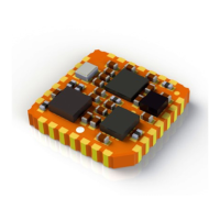
Figure 2: MTi 1-series .............................................................................................................................. 9
Figure 3: MTi 600-series .......................................................................................................................... 9
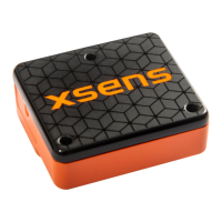
Figure 4: MTi 10-series ............................................................................................................................ 9
Figure 5: MTi 100-series .......................................................................................................................... 9
Figure 6: MTi Development Kit .............................................................................................................. 11
Figure 7: Default coordinate system of MTi 1-series ............................................................................. 16
Figure 8: Default coordinate system of MTi 600-series ......................................................................... 16
Figure 9: Right hand rule ....................................................................................................................... 17
List of Tables
Table 1: MTi product documentation overview........................................................................................ 7
Table 2: Xsens MTi portfolio overview. ................................................................................................. 10
Table 3 Description of hardware components of Development Kit ....................................................... 11
Table 4 Description of software components of Development Kit......................................................... 12
Table 5: Conditions for the use of the MT Software Suite ..................................................................... 13
Table 6: Data outputs with reference coordinate systems .................................................................... 16
Table 7: Yaw in different coordinate systems (applies only to VRU/AHRS and GNSS/INS product types).
The MTi is assumed to be mounted with its roll-axis (X) aligned with the roll-axis of the vehicle (front of
the vehicle). ........................................................................................................................................... 18
Table 8: Output specifications ∆q and ∆v outputs ................................................................................. 20
Table 9: Output specifications inertial and magnetometer data outputs ............................................... 20
Table 10: Output specifications high rate calibrated inertial data outputs ............................................. 20
Table 11: Supplementary features and settings .................................................................................... 24
Table 12: overview of interface options in MTi portfolio ........................................................................ 26


 To Next Page