DS800 Page 5
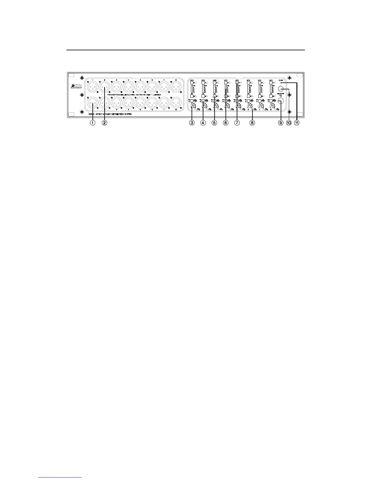
Front Panel Functions
1. Isolated Outputs – two identical transformer balanced outputs featuring high
voltage isolation, for use as broadcast or recording feeds or wherever
independent outputs are required. These connections are wired as follows :-
Pin 1 = No Connection, Pin 2 = Hot, Pin 3 = Cold.
2. As Above.
3. Gain Switch – sets the channel gain to +10dB, +20dB, +30dB, +40dB or
+50dB. See Mic/Line switch below.
4. Mic/Line – when in the ‘Line’ position the input is padded by 20dB and the input
impeadance changes to >10k Ohms.
5. 48V – when selected applies 48V phantom power to the input XLR, for
condenser microphones or D.I. boxes. The LED is lit when active.
6. Meter – 5 segment level meter showing the level below clipping. Note: the red
LED lights up 6dB’s below actual clipping with a sine wave.
7. Listen – when selected the channel will be summed on to the ‘Solo’ bus, which
is routed to the headphone socket and ‘Solo Out’ XLR.
8. Pad (-10dB) – indicates 48V phantom power detected on the output ‘Mon’ XLR,
which will automactically switch in a 10dB pad on the channel.
9. Headphone Level – controls the level of the headphone output.
10. Headphone Socket.
11. Power – power indicator.