MB550 Indoor Cycle
5
1. Using a razor knife (Box Cutter) cut the outside, bottom, edge of box along the dotted Line. Lift
Box over the unit and unpack.
2. Carefully remove all parts from carton and inspect for any damage or missing parts. If damaged
parts are found, or parts are missing, contact us immediately.
3. Locate the hardware package. Remove the tools rst. Remove the hardware for each step as
needed to avoid confusion. The numbers in the instructions that are in parenthesis (#) are the item
number from the assembly drawing for reference.
Pre-Assembly
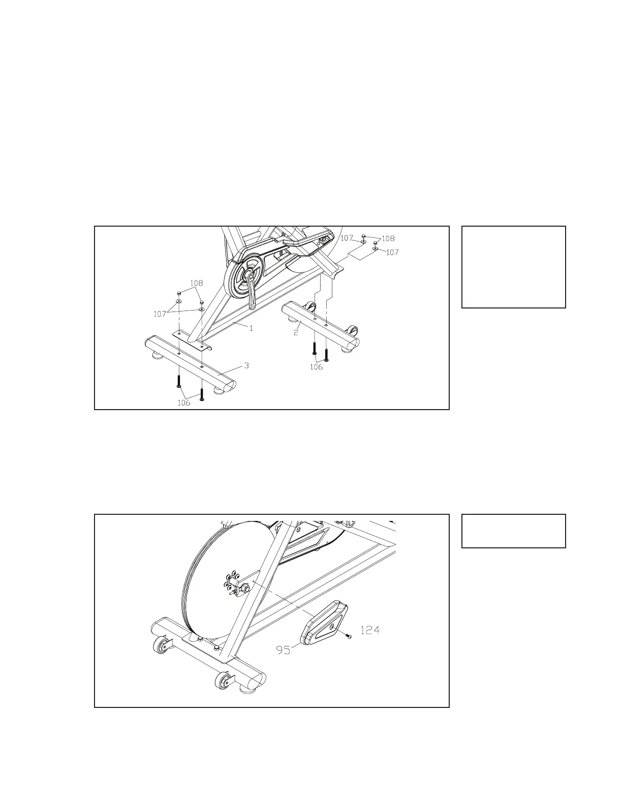
Hardware Step 1
1. Install the front and Rear Bar (2) (3) with four Carriage Bolts (106), four
Flat Washers (107) and four Cap Nuts (108). The front and rear stabiliz-
er are different. Be sure to assemble the stabilizer with the wheels onto
the front of the bike. by using 14/15mm Wrench (109).
Stabilizer Tubes
#106. 3/8” x 2
Carriage Bolt (4 pcs)
#107. 3/8” x 19 x 1.5T
Flat Waher (4 pcs)
#108. 3/8”
Cap Nut (4 pcs)
MB550 Assembly Instructions
1. Install the Cover Front (L)(95) with one Phillips Head Screw (124) by us-
ing Combination M5 Allen Wrench & Phillips Head Screw Driver (117).
Hub Cover
2
1
Hardware Step 2
#124. M6 x 12mm
Screw (1 pcs)
 Loading...