EasyManua.ls Logo

Xtool EZ400PRO User Manual

Xtool EZ400PRO
25 pages
To Next Page IconTo Next Page
Page #1 background imageLoading...
Page #1 background image
EZ400PRO Diagnosis System
1
Declaration
1. The manual is designed for the usage of EZ400PRO, applying to EZ400PRO automotive
diagnosis platform.
No part of this manual allowed to be reproduced, stored in a retrieval system or transmitted, in
any form or by any means (electronic, mechanical, photocopying, recording, or otherwise),
without the prior written permission of Xtool.
2. This electronic control system diagnostic unit is for professional vehicle maintenance
technicians. It has some reliability, but it can not rule out vehicle damage and loss, caused by
customer technical problems, vehicle problems or other factors, for these reasons, users need
to take risks.
3. Use the device only as described in this manual. The user will be responsible solely for the
after-effects of violating the laws and regulations caused by using the product or its data
information, Xtool will not bear any legal responsibility for that.
4. Xtool shall not be liable for any incidental or consequential damages or for any economic
consequential damages arising from the accidents of individual users and the third parties,
misuse or abuse of the device, unauthorized change or repair of the device, or the failure
made by the user not to use the product according to the manual.
5. All information, specifications and illustrations in this manual are based on the latest
configurations and functions available at the time of printing. Xtool reserves the right to make
changes at any time without notice.
6. is the registered trademark of Shenzhen Xtooltech Co., Ltd.
7.In the countries that the trademarks, service marks, domain names, logos and the name of
the company do not be registered, Xtool claims that it still reserves the ownership of the
unregistered trademarks, service marks, domain names, logos and the company name. All
other marks for the other products and the company’s name mentioned in the manual still
belong to the original registered company. Without written permission from the trademark
holder, no one shall use the trademarks, service marks, domain names, logos and company
name of Xtool or other companies mentioned
8. Please visit http://www.xtooltech.com for more information about EZ400PRO.
9. Xtool reserves the right for the final interpretation of this manual content.
Question and Answer IconNeed help?

Do you have a question about the Xtool EZ400PRO and is the answer not in the manual?

Xtool EZ400PRO Specifications

General IconGeneral
BrandXtool
ModelEZ400PRO
CategoryDiagnostic Equipment
LanguageEnglish

Summary

CHAPTER I About EZ400PRO

1. Appearance

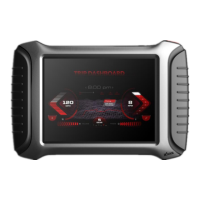
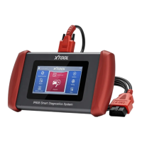
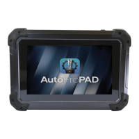
Overview of the device's physical look and design.

1.1. Front View

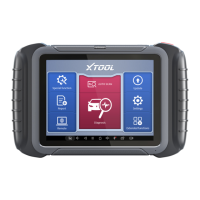
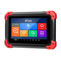
Detailed view of the front panel of the EZ400PRO tablet.

1.2. Back View

Detailed view of the back panel of the EZ400PRO tablet.

2. Layout of EZ400PRO Tablet

Diagram showing the arrangement of components on the EZ400PRO tablet.

2.1. Top View of EZ400PRO Tablet

Illustration of the top side of the EZ400PRO tablet and its ports.

3. Layout of VCI Box

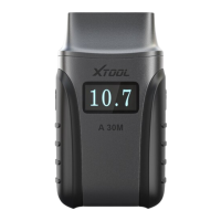
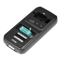
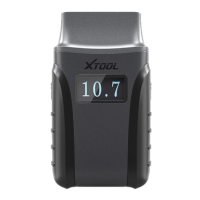
Diagram illustrating the physical layout of the VCI Box.

4. EZ400PRO Technical Parameters

Specifications including OS, processor, memory, display, power, and dimensions.

CHAPTER II How to use EZ400PRO

1. EZ400PRO Activation

Step-by-step guide for activating the EZ400PRO device.

1.1. Please activate EZ400PRO before you use it to test vehicles.

Instruction to activate the device prior to vehicle testing.

1.2. Connect to WiFi first.

Requirement to connect to a WiFi network for activation.

2. EZ400PRO Main Interface and Functional Buttons Descriptions

Overview of the main screen and key operational buttons.

2.1. Main Interface

Visual representation of the EZ400PRO's primary user interface.

2.2. Sub-menus and Function Buttons

Explanation of navigation menus and their associated functions.

2.3. Toolbar Function Buttons

Description of buttons found in the toolbar for navigation.

3. Vehicle Connection Diagnosis

Process for establishing a diagnostic connection with a vehicle.

3.1. Vehicle Connection Test

Procedure to verify the connection between the tool and the vehicle.

3.1.1. Wired Connection ①→② ③ ④

Detailed steps for establishing a wired connection with the vehicle.

3.2. Precautions Before Use

Important guidelines and warnings before operating the device.

3.2.1. The vehicle power supply has to meet the normal voltage limits DC4.8V---5V.

Specific requirement for the vehicle's power supply voltage.

4. Diagnosis

Core diagnostic functions and operations of the EZ400PRO.

4.1. Menu Options

Explanation of the diagnostic menu structure and navigation.

4.2. Test Functions

Detailed descriptions of various diagnostic test functions available.

4.3. Read ECU

Function to retrieve ECU identification and version information.

4.4. Read DTCs

Procedure to read Diagnostic Trouble Codes (DTCs) from the ECU.

4.5. Clear DTCs

Function to erase stored Diagnostic Trouble Codes from the ECU.

4.6. Read Live Data

Display of real-time vehicle operating parameters and sensor data.

4.7. Special Functions

Access to advanced diagnostic functions specific to certain vehicles.

4.8. Actuatation/Ative/Components Test

Tests to verify the operation of vehicle actuators and components.

5. Settings

Units: Select unit of measurement. Users can tick Metric or English measurement.

Setting the preferred measurement units (Metric or English).

System Settings: Android system setup, such as wireless, audio frequency, light sensation, etc.

Configuration of Android system parameters like network and display.

6. Diagnostic Reports

6.1. PDF Files:

Accessing diagnostic reports saved in PDF format.

6.2. Pictures:

Viewing screen capture images taken during diagnosis.

6.3. Data Playback:

Replaying recorded live data and freeze frames from past tests.

7. UPDATE

8. Xtool Cloud System(Coming soon)

9. Remote Access

CHAPTER III Diagnostic Link Connectors of Different Vehicle Models

1. Diagnostic Link Connectors Diagram of Some Vehicle Models

Visual representations of OBD connector locations for various car models.

2. Location Diagram of Vehicle Diagnostic Link Connectors

Diagrams illustrating the placement of diagnostic ports in different vehicle types.

3. Diagnostic Link Connectors Terminal Definition and Communication Protocols

Technical details on pin assignments and communication standards for diagnostic connectors.

3.1. Standard OBDII Diagnostic Link Connector:

Specific information on the standard OBDII connector pinout.

Related product manuals