VESDA VFT Product Guide
VESDA by Xtralis
24 www.xtralis.com
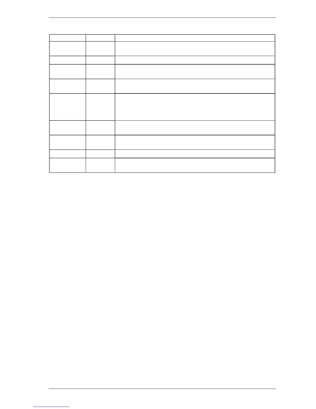
Table 5-3: Engineering Parameters and Values
Parameter Value Description
VERSION *.** Version of Software in the processor module in the Main Unit. The software
can be upgraded using a PC and a special interconnect lead.
BUILD NO *.** Reference to specific software build.
GENERAL
FAULT
*.** Fault list that generates fault number codes.
DETFLOW **.*% Sample flow through the detector. This measurement may be
enabled/disabled under Configuration.
FLOWnn **.*% Measurements of Sample flow rates for each sector. The number will vary
depending on the number of actual sectors sampled. The flow rates should
be normalized to 100% at installation. High pressure systems measure
pressure for each sampled sector.
BATTERY **.*V Measurement of backup battery voltage. Applies to internal power supply
units only.
OBS/M or
OBSC/FT
*.**% Obscuration value in meters or feet. This is the same as the normal display.
To change from metric to imperial see Section 5.3.8.
REFDENS *.**% For special applications only.
MODn 1 to 5 Shows the module types that are fitted. These are read directly from the
Modules.
5.3.4 CONFIGURE: Configuration Mode
Minimum Access Code Required: Level 1
The VFT detector uses many configuration parameters, and is shipped with factory default values. The
Configuration Mode allows changes to be made to these parameters. Below is a list of user definable
parameters, and their Factory Default values. The Parameter UP and DOWN buttons (Isolate and Scan)
navigate through the list; the Value UP and DOWN buttons (Accept and Reset) change the value. The
ENTER button (Sounder Silence) saves the new value, and moves to the next parameter.
 Loading...