VESDA by Xtralis
VESDA VFT Product Guide
www.xtralis.com 53
D Communications Guide
This section describes how to set up the detector for monitoring and configuration from a PC, and also how to
connect the detectors together in a network. VESDA VFT detectors support three types of communication
systems:
l TCP/IP - for connecting a PC to one or more VFT detectors via Ethernet
l RS232 - for connecting a VFT detector directly to the PC
l RS485 - for connecting between VFT detectors, or a VFT detector to a PC via a RS485/RS232
converter
D.1 TCP/IP Communications
The TCP/IP interface on the VFT detector enables the monitoring and configuration of a large number of
detectors from one PC via a standard internet connection.
To set up the detector for TCP/IP communications to a PC with Xtralis VSC or VSM4 software, you will need
standard Cat 5 Ethernet cables for connecting the PC Ethernet port to a LAN/WAN point, and each detector's
Ethernet port to a LAN/WAN point.
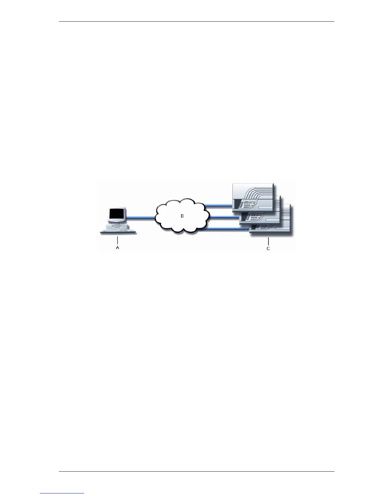
The following figure illustrates the connection between PC and one or more detectors via TCP/IP.
A. PC with Xtralis VSC
or VSM4
B. LAN/WAN C. Connected
detector(s)
Figure D-1: PC to one or more detectors via a TCP/IP connection.
In order to connect multiple detectors to a PC, each device on the network needs to have a static IP address.
The IP address for the VFT detectors are configured using a direct RS232 serial connection. For more
information on the RS232 connections, refer to Section D.2.
On Xtralis VSC or VSM4, the connection type to enable TCP/IP communications is 'Xtralis MODBUS'. For
further details on the configuration and operation of Xtralis VSM4, consult the Xtralis VSM4 Product Guide or
online help.