VESDA by Xtralis
VESDA VFT Product Guide
www.xtralis.com 31
5.3.8 SETUP: Setup Menu
Minimum Access Code Required: Level 2
Once the Setup Mode is accessed, follow this procedure to change a parameter:
1. Press Parameter UP & DOWN buttons to reach required SETUP item.
2. Press ENTER.
3. Press Value UP & DOWN buttons to update the item.
4. Press ENTER to update and move to next parameter. If the value is left unchanged, ENTER will have
no effect.
Press MENU to get back to the Main Menu. Press MENU again to get back to Normal display.
The Setup menu has the following items.
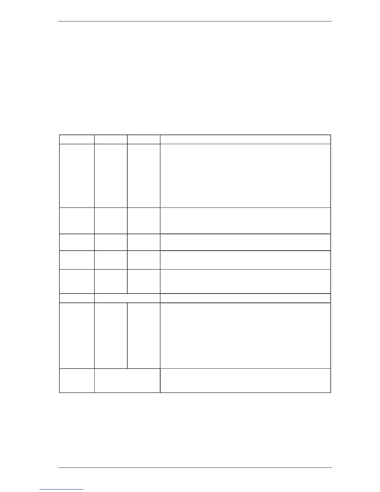
Table 5-6: Setup Menu Parameters and Values
Parameter Value Defaults Description
HI RESLTN 0 or 1 0 Enables the Status Display to show standard resolution (0) or
higher Resolution (1) for obscuration (switches between a
resolution of 0.01 to 0.001).
Note: It is highly recommended to leave this value at 0. Changing
the value from 0 will cause some configuration values to
change. Connection to Xtralis fire configuration and
management software will automatically change this value
back to 0.
OBSC/FT 0 or 1 0 Set to 1 to display smoke value in % obs/ft. Normally % obs/m.
Note: Smoke Alarm Thresholds will revert to default values when
changing between % obs/ft and % obs/m and vice versa.
REMPANEL 0 or 1 0 Enables remote panel operation. A communications fault will be
displayed if this is enabled without a remote display connected.
REMPOD 0, 1 or 2 0 Set to 1 if a Remote Sensing Unit is connected.
Note: This option is not available for standard VFT detectors.
DETFLOW 0 or 1 1 In addition to individual sector flow monitoring, detector flow
monitoring is also incorporated.
Set to 1 to enable.
CCODE Country Code Refer to Table 5-7.
RES-ISOL 0 or 1 1 Set to 0 to reset system with 24 V on reset line.
Set to 1 to isolate system when 24 V is applied for 8 seconds or
more.
Note: Once 24 V is applied, the system will initially reset. If 24 V
is still present after 8 seconds, the system will be isolated
until 24 V is removed (after which it will resume normal
operation). If the 24 V is removed before 8 seconds, the
system will only reset and will not be isolated.
MOD1 to 5 List of available I/O
modules
All I/O modules fitted at build will have this information entered. If
additional I/O modules are installed, their type must be entered
here.
The VFT detector can operate in a number of different languages. To change the language, the correct country
code (CCODE) must be entered.