VESDA by Xtralis
VESDA VFT Product Guide
www.xtralis.com 37
To install and configure the output module, set applicable parameters according to the following table.
Table 5-11: 8-Channel Output Module Configuration Parameters
Menu Item Parameter Value
SETUP (MODULE n) Set to ANOUT 8
CONFIGURE (MOD n) According to Table 5-12.
(GAIN X) Applies to Smoke only.
G = A/O where:
l G = Gain
l A = Maximum Output Current
l O = Obscuration reading
corresponding to maximum
output current
Examples:
l Set GAIN X to 1 for 20%/m
(1 = 20mA / 20%/m)
l Set GAIN X to 10 for 2%/m
(10 = 20mA / 2%/m)
l Set GAIN X to 100 for 0.2%/m
(100 = 20mA / 0.2%/m)
To access the Setup menu, follow these steps:
1. Press MENU.
2. Use Parameter UP and DOWN buttons to reach SETUP.
3. Press ENTER.
4. Use Value UP and DOWN buttons to enter the Level 2 Access Code.
To access the Configure menu, follow these steps:
1. Press MENU.
2. Use Parameter UP and DOWN buttons to reach CONFIGURE.
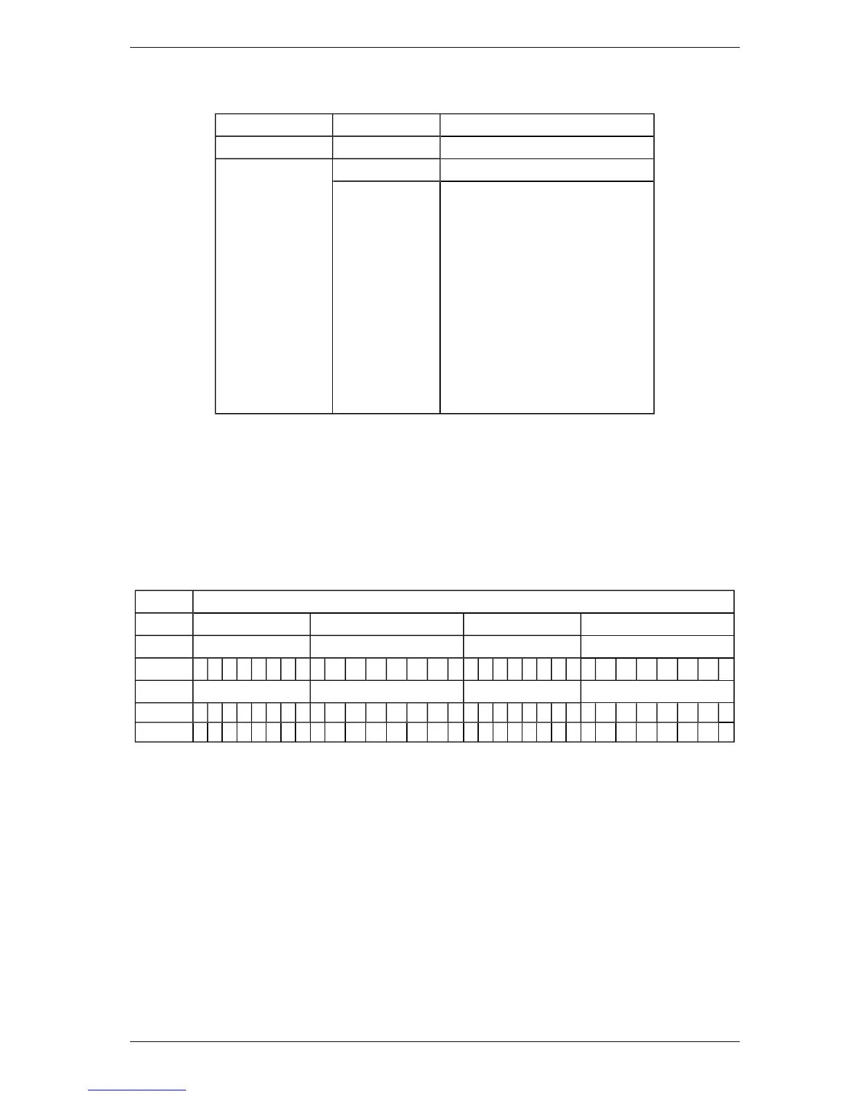
Table 5-12: 8-Channel Output Module setup table. Modules are numbered 1 to 5, left to right.
Analog Output Module
1 2 3 4
Channel Channel Channel Channel
1 2 3 4 5 6 7 8 1 2 3 4 5 6 7 8 1 2 3 4 5 6 7 8 1 2 3 4 5 6 7 8
Config Sector Sector Sector Sector
FLOW X 1 2 3 4 5 6 7 8 9 10 11 12 13 14 15 D 1 2 3 4 5 6 7 8 9 10 11 12 13 14 15 D
SMOKE X 1 2 3 4 5 6 7 8 9 10 11 12 13 14 15 D 1 2 3 4 5 6 7 8 9 10 11 12 13 14 15 D
Note: D = Detector Readings (FLOW X: detector flow; SMOKE X: real time smoke density).
 Loading...