VESDA by Xtralis VESDA PipeNetwork Design Guide
www.xtralis.com 15
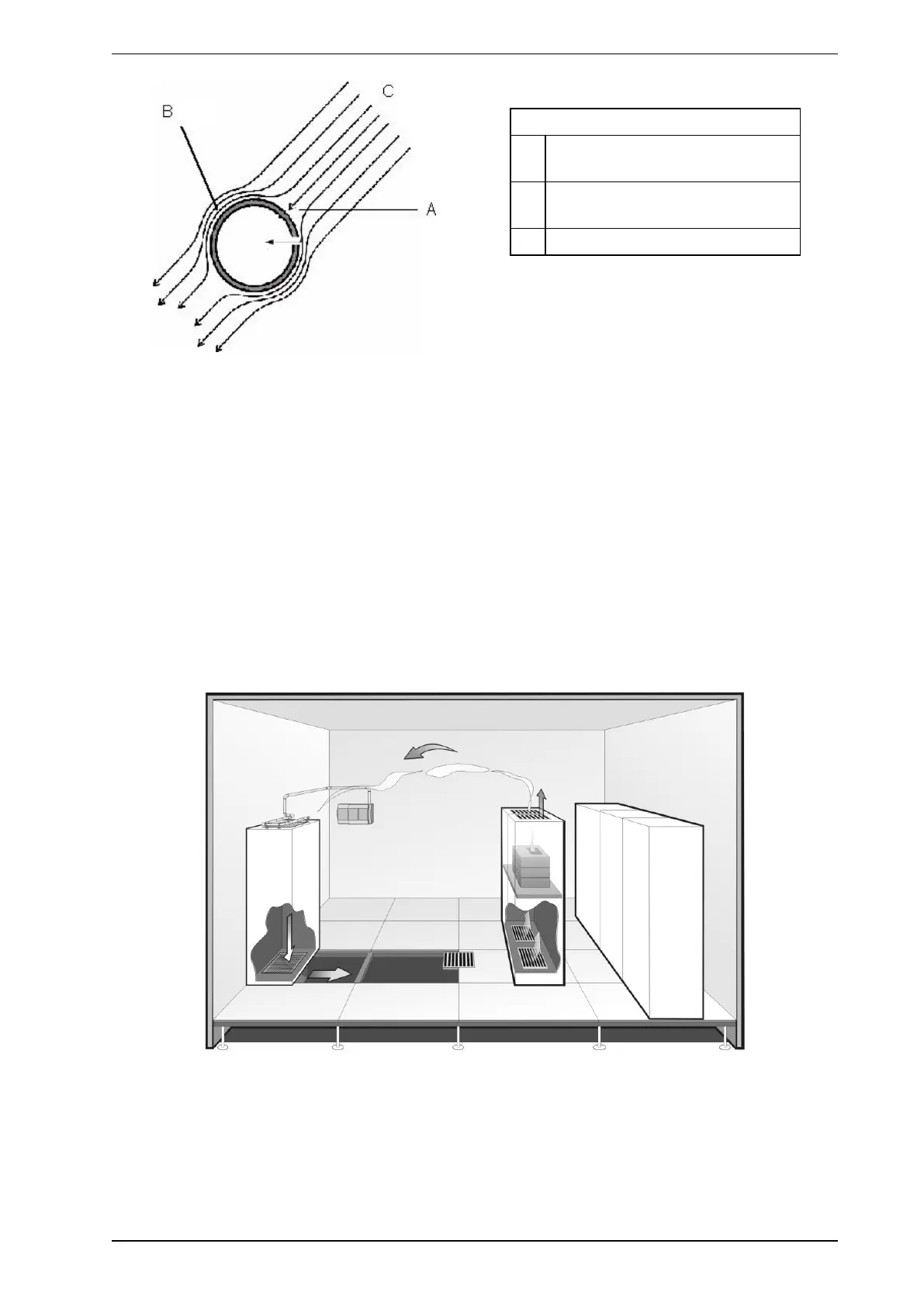
Legend
A Low velocity (high static pressure)
area
B High velocity (low static pressure)
area
C Airflow Streamlines
Figure 4-12: Sampling hole orientation
Note: Socket unions are also used where it is important to have correct orientation of sampling holes.
Guidelines for return air sampling include:
1. Place the sample pipe (probe) in the path of the greatest airflow.
2. More than one sampling hole may be required for large grilles. NFPA 76 recommendations specify that
each sampling hole can cover a maximum of 0.4 m² (4 sq.ft).
3. Care should be taken to keep the number of bends to a minimum.
4. We recommend that sampling holes should be angled at 30 degrees to the airflow.
5. In high velocity air flows, it is advisable to use standoff fittings to keep the sampling pipes at least 50 mm
to 200 mm (2 to 8 in.) in front of the grille. Installing any closer to the grille will put the sample point in an
area of negative air pressure.
6. The pipe will require capping with an end-cap without a hole.
7. Where maintenance requires the removal of the sampling pipes on a regular basis, the pipe network
design should provide for use of socket unions to ensure correct orientation of sampling holes on re-
connection.
Figure 4-13: Typical return air sampling application