VESDA by Xtralis VESDA PipeNetwork Design Guide
www.xtralis.com 45
10.2 Sampling and End Cap Holes
The sampling holes are drilled into the pipe(s), once the pipe network has been installed. Endcaps must
always be placed at the end of each sampling pipe. ASPIRE2 calculations will determine the diameter of each
sampling hole and the end cap hole. The end cap hole can be used as another sampling hole, but is generally
used to improve the transport time for the pipe. The diameter of the end cap hole is determined by the
parameters of the pipe network, such as the pipe length and the number of sampling holes.
10.3 Pipe Connections
10.3.1 Joints
Pipe joints must be airtight. Glue together the pipes once the final form of the network has been determined.
Do NOT glue the pipes to the pipe inlet and exhaust manifolds of the detector. The use of excessive amounts
of glue can block or partially block pipe airflow to the detector and severely affect the detectors ability to
detect smoke. Testing must be conducted after the pipes are glued together.
10.3.2 Bends
We recommend bends and elbows are used to change the direction of the pipe. Wide radius bends are
preferred to elbows. Good pipe network designs keep the number of bends and elbows to a minimum as they
interfere with the optimum airflow. We recommend you use multiple pipes instead of bends and elbows.
Figure 10-1 illustrates the advantage of multiple pipes over bends and elbows.
10.3.3 Tees, Y-pieces and J-Pieces
Tees, Y-pieces and J-pieces are used to branch the trunk pipe line. These may also be used for connecting
capillary tubes and drop pipes.
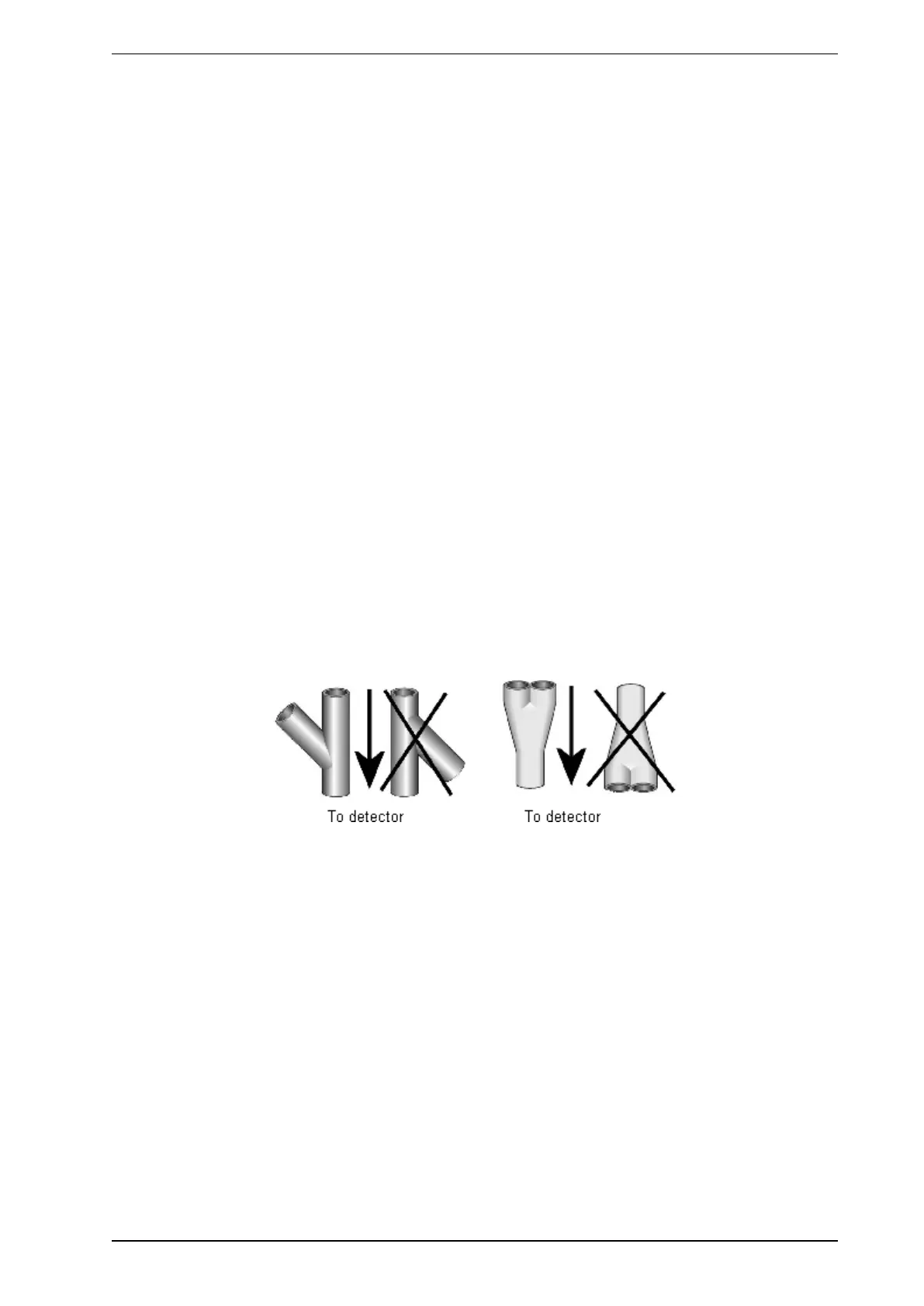
Y-pieces and J-pieces must NOT be branched towards the detector. Branching against the natural airflow will
disrupt the flow of air in the pipe and lead to unpredictable results.
Figure 10-3: Correct placement of Y-pieces and J-pieces