VESDA PipeNetwork Design Guide VESDA by Xtralis
30 www.xtralis.com
6.1.1 Sampling Hole Conventions
The below example relates to NFPA 72 requirements:
1. The typical maximum size for a fire zone is 2000 m² (20 000 sq.ft)
2. The maximum area covered by a sample point is 82.81 m² (891 sq.ft)
3. The sample hole will not be more than 4.55 m from walls (14.56 ft)
4. The maximum space between sampling holes is 9.1 meters (29.12 ft)
5. A sample point shall not be more than 6.4 meters (20.4 ft) from any point in the room
Plot the remaining sampling holes for the row. Normally these will be spaced at equal distance from each
other.
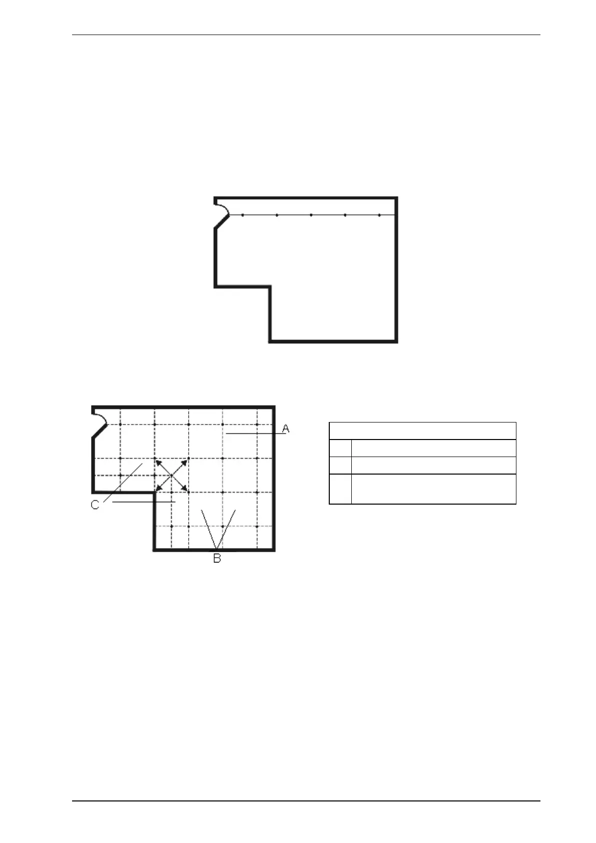
Figure 6-2: Plotting the first row of sampling holes
Plot sampling holes in equidistant parallel rows to form squares. If the area to be plotted is irregularly shaped a
combination of square and/or rectangular plotting may be required.
Legend
A Square plotting of sampling holes
B Grid overlay
C Rectangular plotting of sampling
holes
Figure 6-3: Square and rectangular plotting of sampling holes
After plotting the sampling holes determine the optimum positioning of the VESDA detector keeping in mind
the good design principals of:
l Shorter multiple pipe runs. To find out why this is critical, refer to the System Performance Graph in
Figure 10-2 on page 44.
l Minimum changes in pipe direction
Next plot the pipes on to the site plan by joining the holes and terminating these at the detector.