VESDA Commissioning Guide VESDA by Xtralis
22 www.xtralis.com
1. Ensure that the local fire panel is isolated from the external fire reporting equipment and that any
automatic extinguishing or suppressant systems are also isolated.
2. With the power turned off, connect each end of a 1 meter (3 ft.) length of the specified wire to the VTT-
10000.
3. Ensure that the wire is laid on an insulating board to avoid damage to the floor.
4. Check that there are no kinks or crossovers in the wire.
5. Connect power to the VTT-10000 and turn the power on for 180 seconds.
At this point, there is 6 VAC applied across the test wire, the switch will illuminate and the green indicator on
the timer will begin to flash. The test wire will become hot and a small quantity of smoke will be generated.
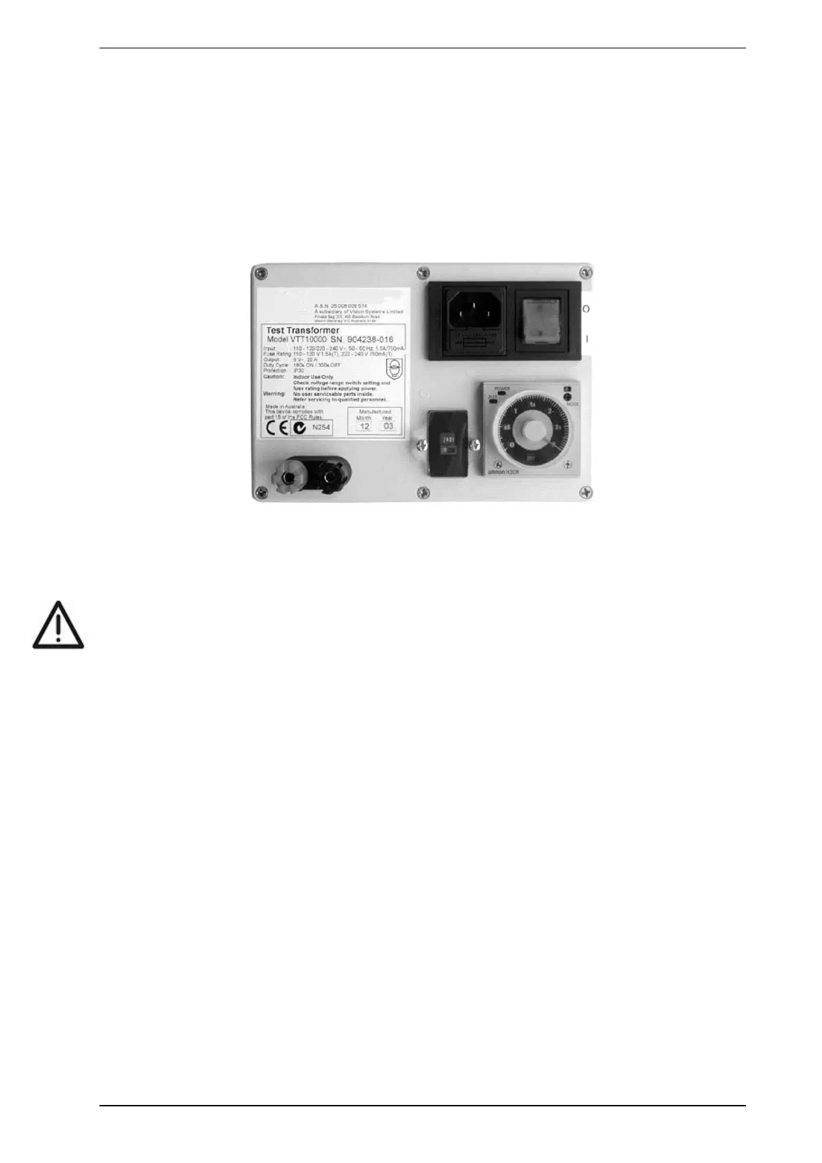
6. Turn the unit off after the timed burn period is complete.
Figure 5-3: Wire Burn Test Kit VTT-10000
7. Record the response time of the detector.
8. For multiple tests, allow 5 minutes (300 seconds) between tests so all smoke can dissipate.
Caution: The test wires will become very hot. Do not touch.
Enter the following results on the commissioning form:
l Transport Time - Introduce smoke at the furthest sampling hole from the detector. The time taken (in
seconds) for the smoke to travel to the detector is the transport time. If there is a wide variation between
the ASPIRE2 predictions and the test results, the pipe network should be checked for leaks, blockage
and to see that the installed pipe network matches the model used in ASPIRE2.
l Initial Response - This is the total of the time taken for the smoke to travel from the source to the
sampling point and the detector first registering the presence of smoke (excluding any alarm delay times
that may have been set).
l Alert Response - The time taken for initial response and the detector to generate an Alert Alarm
l Action/Pre-Alarm - The time taken for alert and the detector to generate an Action/Pre-Alarm status
(excluding any delay times)
l Fire 1/Fire Response - The time taken for alert and the detector to generate an Fire 1/Fire Response
status (excluding any delay times)
l Fire 2 Response - The time taken for alert and the detector to generate an Fire 2/Fire Response status
(excluding any delay times)
l Peak Smoke Response - This is the time taken for the detector to record the peak level of smoke
(excluding any delay times). The numerical display of the display module or the LCD Programmer will
display the smoke levels. This information can also be extracted from the event log.
Acceptable response times are determined by site requirements, subject to local codes and standards. In the
event the test response times do not meet the acceptable standard the commissioning form should be signed
as NOT ACCEPTABLE and recommendations for further work should be recorded on the commissioning
form.