Operation Manual69
Operation
NOTE: The boom angle indicator is a plumb arrow with
angular graduations from -5 to +70.
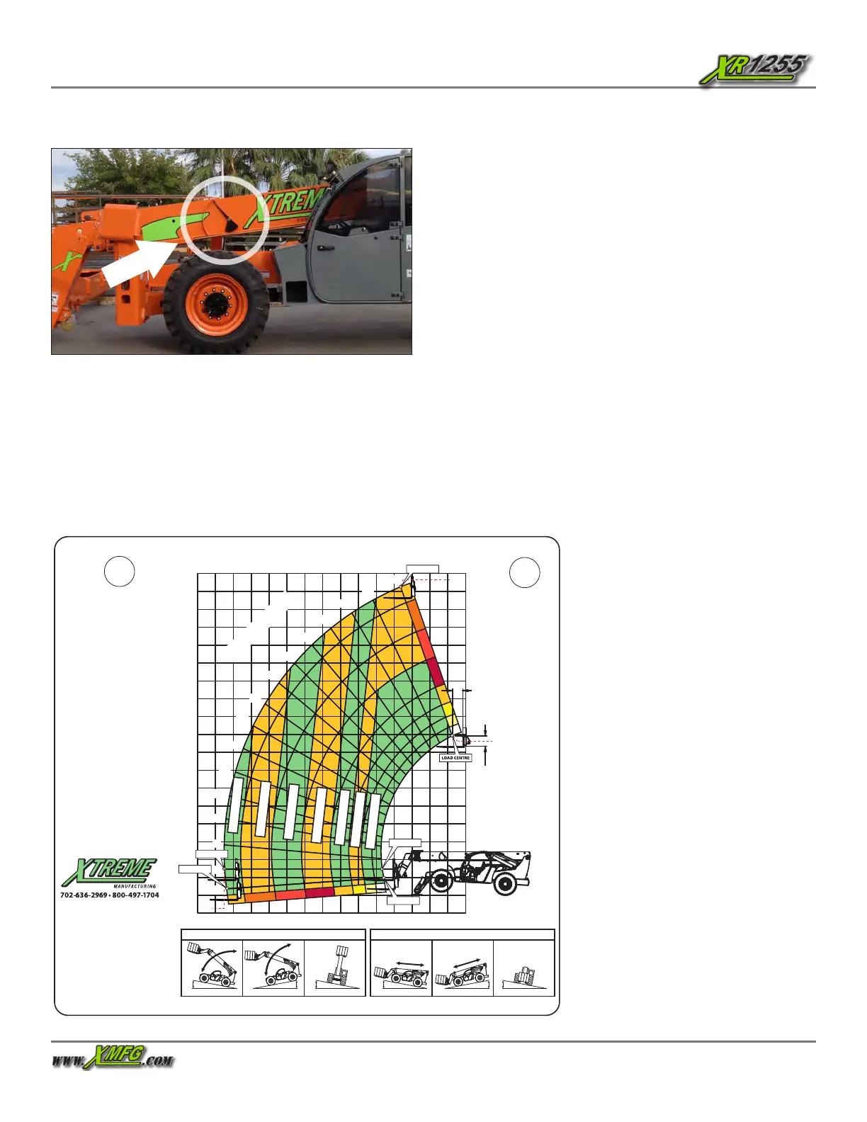
Figure 88. Boom Angle Indicator
Reading Load Capacity Charts
To accurately read the load capacity charts, you must
determine three (3) things:
• Weight of the load being lifted
• Height of structure where load is to be placed
• Distance from front tires where load will be placed
For example:
1. The operator determines load weight and makes sure load
does not exceed fork, attachment, or boom capacity.
The load is 6,614 lbs.
2. The operator safely moves the load to a loading position.
• places forks under load
• tilts and raises load safely
• fully retracts boom
• drives forklift to position perpendicular to structure
• levels the forklift
3. The operator determines height of structure where load is
to be placed.
The structure height is 26.2 feet from ground level.
4. The operator determines distance from front tires where
load will be placed.
The distance in front of forklift where load will be placed is
19.6 feet.
5. Operator reads load capacity chart for attachment carriage
to learn it will be safe to place the load at any boom angle with
the boom extend letter “E” showing.
PICK & CARRY INFORMATION: MACHINE POSITION - BOOM FULLY RETRACTED WITH RATED LOAD NO MORE THAN 300MM ABOVE GROUND
TRAVEL SPEED WITH RATED LOAD - 0.4M/S WALKING SPEED
LIFTING (STATIONARY) - RATED LOAD ON FORKS
TRAVELLING (PICK & CARRY) - RATED LOAD ON FORKS
4º MAX
4º MAX
10º MAX
10º MAX
5º MAX
XR1255 LOAD CHART OUTRIGGERS DOWN - STANDARD CARRIAGE
LOAD HEIGHT METER
REACH METER
THE
CHASSIS
MUST
REMAIN
LEVEL
LOAD CHART
P/N 17251-100
REV 00
NO OPERATION
ABOVE 55 DEGREES
BOOM ANGLE WITH
REAR AXLE UNLOCKED.
LOAD RATINGS
SHOWN ARE FOR
VEHICLES EQUIPPED
WITH FOAM FILLED
TYRES ONLY.
2,720 KG AT
600MM MIN
CAPACITY FORK
(5,440 KG PAIR).
SPECIFICATIONS FOR SAFE USE
TYRE SIZE: 15.5 X 25 (G2 or E3 FOAM FILLED)
MAX WHEEL LOADING: 9400 KG
MINIMUM TYRE MASS: 435 KG
IN SERVICE WIND SPEED: 10 M/S - 36KM/H
FORK LOAD CENTRE: 600 MM
GROUND CONDITIONS: SOLID SURFACES
FOR BOTH LIFTING AND TRAVELLING, SLOPE
RATINGS LISTED FOR BOTH CONDITIONS
STANDARD USED: (AS 1418.19)
CARRIAGE P/N
25419-010
FORK DIMENSIONS (MM)
102 X 57 X 1524
H
G
F
E
D
B
C
A
H
F
B
E
D
C
A
G
0
12
7
6
5
4
3
2
8
9
10
11
1
15
13
14
18
16
17
-2
-10
1
2
3
4
5
6
7
8
9
10
11
12
13
35
50
65
25
71
0
55
60
20
15
10
30
40
45
5
5
BO O M ANGL E
600MM
LOAD
CENTRE
600MM
LOAD
CENTRE
3,050 KG
2,250 KG
1,800 KG
3,850 KG
4,500 KG
1,300 KG
5,440 KG
LOAD CENTRE
17.2
8.9
LOAD CENTRE
LOAD CENTRE
LOAD CENTRE
11.5
LOAD CENTRE
Figure 89. Load Capacity Chart
 Loading...