WARNING:
Do not install the starter equipment in an explosive zone unless it is explosion-proof rated.
Three thermal contacts are incorporated in the stator. They are normally closed.
Thermal contacts must never be exposed to voltages higher than 250 V, breaking current
maximum 6 A at a power factor 0.6. It is recommended that the thermal contacts are
connected to 24 V over a separate fuse to protect any other automatic equipment.
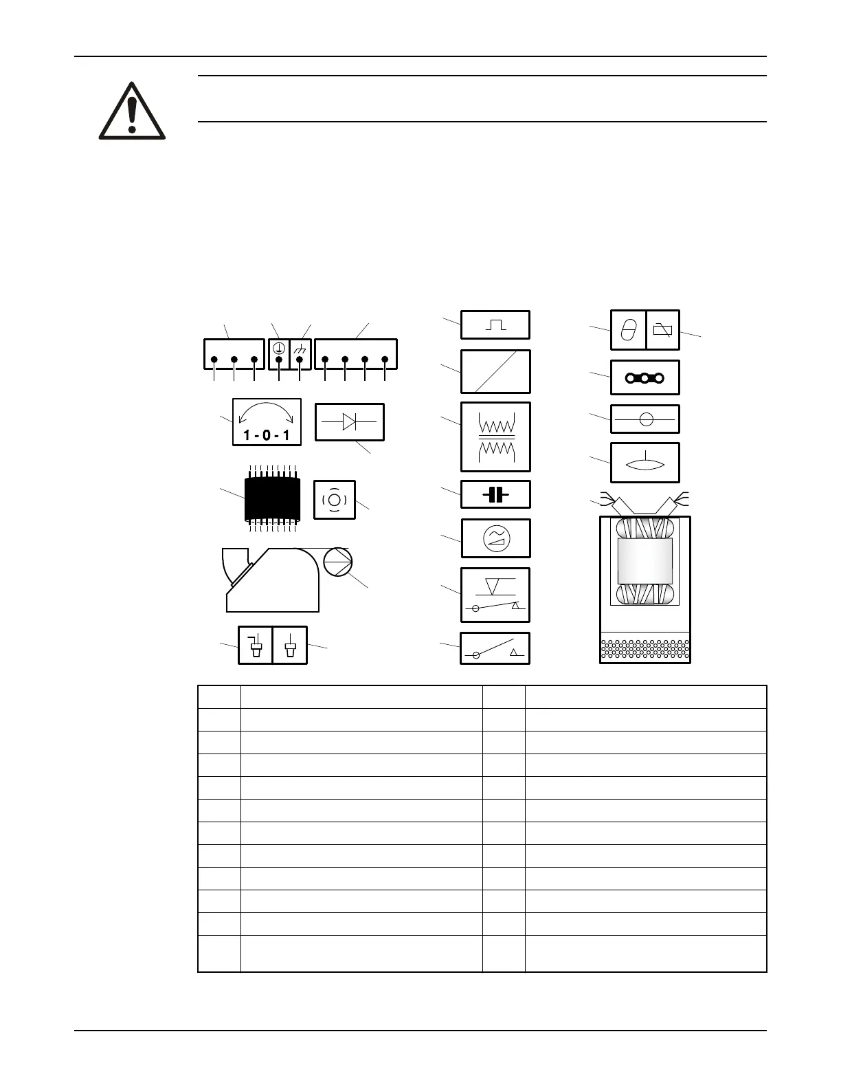
Cable charts
Connection locations
WS001021B
L1 L2 L3
T3 T4T1 T2
15
13
14
42 31
7
10
5
9
8
6
11
12
17
16
24
22
23
19
20
21
18
1 Starter equipment and main leads (L1, L2, L3) 13 Coil
2 Earth (ground) 14 Transformer
3 Functional ground 15 Capacitor
4 Control leads (T1, T2, T3, T4) 16 Softstarter
5 Phase shifter 17 Level regulator
6 Diode 18 Contactor, start relay or thermal relay
7 Motor cable, minimum 20 m (66 ft.) 19 Thermal detector in stator
8 Screen 20 Thermal detector in main bearing
9 Pump 21 Jumper
10 Crimp connection 22 Terminal board, terminal plate
11 Crimp isolation 23 Leakage sensor
12 Motor protector 24 Stator leads (U1, U2, U5, U6, V1, V2, V5, V6,
W1, W2, W5, W6, Z1, Z5, Z6)
Installation
Flygt 2250 Installation, Operation, and Maintenance Manual 17
 Loading...