1
2
3
4
L1 L2 L3
T3 T4T1 T2
U1
V1
W1
U2
W2
V2
U1
V1
W1
W2
U2
V2
U1
V1
W1
GC
W2
U2
V2
L1
L2
L3
*YE
GN/YE
WH
L1
U1
U2
W2
V2
W1
V1
L3
L2
WS004133D
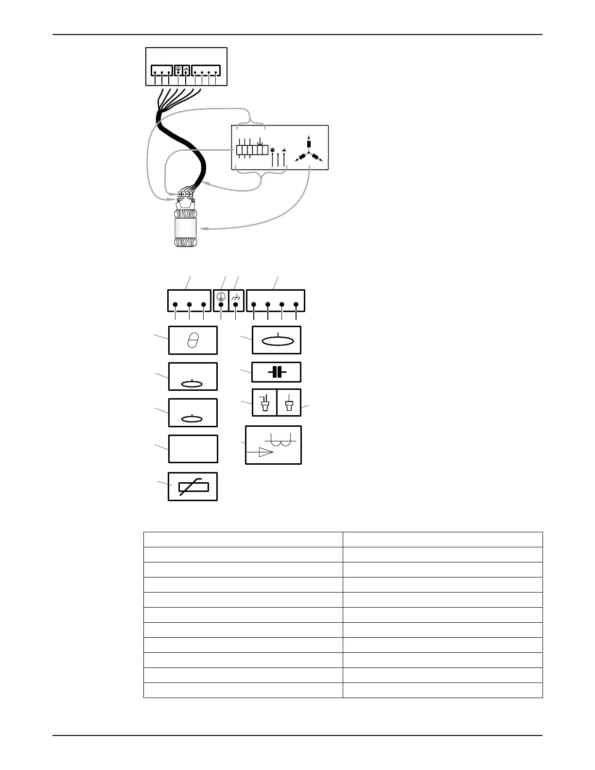
1. Stator leads
2. Terminal board
3. Power cable leads
4. Stator (internal connection illustrated)
L1 L2 L3
T3 T4T1 T2
43
21
5
10
8
CLS
6
FLS
7
FLS 10
11
9
WS004134B
12 13
14
CT
1. Starter equipment and mains leads (L1, L2, L3)
2. Ground (earth)
3. Functional ground
4. Control leads (T1, T2, T3, T4)
5. Thermal contact
6. FLS
7. FLS 10
8. CLS
9. Thermistor
10.Level sensor
11.Capacitor
12.Crimp connection
13.Crimp isolation
14.Current transformer
Color code standard
Code Description
BN Brown
BK Black
WH White
OG Orange
GN Green
GNYE Green-Yellow
RD Red
GY Grey
BU Blue
YE Yellow
4 Installation
32 Flygt 3102 Installation, Operation, and Maintenance Manual

 Loading...