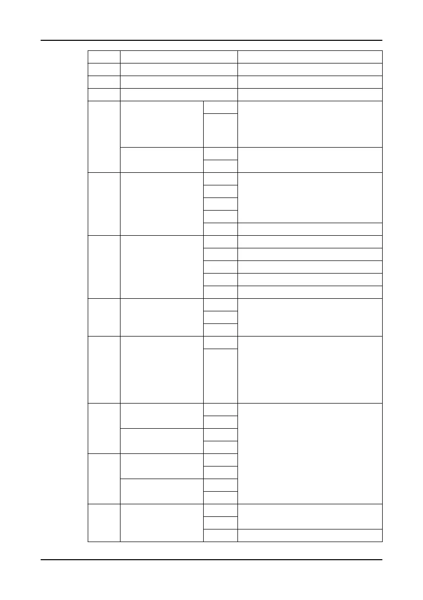
Section Terminal Description
2 TERM Backplane termination switch
3 USB Standard type A USB socket
4 MASTER, SLAVE MASTER/SLAVE switch
5 AI + Isolated analog input, 4–20 mA
Maximum 24 VDC
Scaling: 0–100%
Offset: 0–16 mA with 0.1 mA resolution
–
AO + Analog output, 4–20 mA
Maximum 24 VDC
–
6 DI 1 Digital inputs
Maximum 24 VDC
2
3
4
GND Common ground (earth)
7 HMI
• Flygt FOP 315
1 Ground
2 CAN low
3 Shield
4 CAN high
5 + 24 VDC output
8 RS-485 A Modbus RTU
B
GND
9 24 VDC + 24 VDC
Tolerance: 21.5–28.5 VDC
The power supply unit must fulfill isolation class
II.
< 700 mA. Typical: 150 mA
Fuse: 1 A
–
10 DO3 NO Digital outputs
Potential free relay output
Maximum 250 VAC, or 30 VDC, 5 A
External fuse required, 5 A
COM
DO4 NO
COM
11 DO1 NO
COM
DO2 NO
COM
12 – T4 Mixer/pump communication
T3
GND Not used
9 Technical Reference
APP 412 Installation, Operation, and Maintenance manual 29
 Loading...