Do you have a question about the Yakima LockNLoad Series and is the answer not in the manual?
Clean and dry the vehicle roof thoroughly before commencing the track installation process.
Position the foam tape outwards and ensure cut-outs are at the rear of the vehicle.
It is recommended to install one track at a time for optimal results.
Measure and mark 1420 mm and 230 mm from the windscreen rubber edge.
Drill three holes at marked locations through the trim, taking care not to penetrate the roof.
Use masking tape and tin snips to carefully cut through the middle of the rubber roof channel trim.
Bend the cut trim sections back and forth at drilled holes to break them cleanly.
Remove paint and tape from M8 mounting points; file if necessary for screw access.
Place track in channel, align, and insert M8 screws to hold it for spot drilling.
Drill rivet holes using a 4.9mm drill bit, working from the rear of the vehicle forward.
Drill all rivet holes using a drill stop to avoid damaging the roof lining.
Use a vacuum cleaner to remove metal shavings (swarf) from the roof channel.
Apply galvanizing solution and then silicone sealant to all drilled holes for protection.
Accurately position the tracks over the drilled holes, ensuring correct orientation.
Insert M6 screws through nut plates and slide them into the track ends.
Assemble the End Caps into the tracks, paying attention to their orientation.
Assemble M8 washers and screws, then tighten to secure end caps and track.
Confirm that both tracks are securely fastened to the vehicle according to instructions.
Spot drill specific M8 mounting points on the track for Isuzu D-Max SX models.
Open out spot-drilled mounting points using a 7mm drill bit for SX models.
Die grind opened holes to expose the M8 mounting points for SX models.
Vacuum swarf from newly drilled holes in the roof channel for SX models.
Apply Zinc Rich Cold Galvanising Solution to SX mounting holes.
Remove Plastite screws and pull End Caps from the ends of LockNLoad Bars.
Use supplied keys to remove all Leg Covers from the LockNLoad Leg Kit.
Slide pre-assembled Leg assemblies into the underside channel of LockNLoad Bars.
Identify desired positions for front and rear bars, ensuring 700mm minimum spacing.
Place bar assembly over nut plates, aligning legs into cut-outs, without damaging the vehicle.
Insert M6 Hex Screws through outer holes on Legs into Nut Plates.
Ensure even bar overhang by sliding bars along legs, re-adjusting as needed.
Tighten all M8 Set Screws to 9 Nm using a 13 mm spanner.
Repeat steps for the second bar assembly and remove all assemblies from the vehicle.
Measure leg-to-slot distance on bars, ensuring consistency between ends.
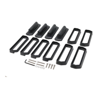
Cut and press bar slot covers into the underside channel of bar ends.
Cut and fit remaining slot covers to the bar channel outside the legs.
Insert End Caps into bar ends, using a rubber mallet if needed.
Secure End Caps using Plastite Screws tightened with a Phillips screwdriver.
Slide nut plates into tracks and place bar assembly, aligning legs into cut-outs.
Assemble M6 spring and regular washers onto M6 Hex Screws for attachment.
Tighten M6 Hex Screws to 5 Nm using a 10 mm open-ended spanner.
Verify that all Bar Legs are securely fastened to the vehicle.
Fit and lock all Leg Covers using the supplied keys and covers.
Record key number and store keys safely for future use.
| Brand | Yakima |
|---|---|
| Model | LockNLoad Series |
| Category | Automobile Accessories |
| Language | English |