12
PIR movement detector
The PIR has a built-in sleep timer to save
battery power. If there is no movement in front of
the PIR for 1 minute, the PIR will become ‘ready
to signal’ and any movement will now be
reported. The PIR will sleep for 1 minute after.
Any movement detected in sleep time will not be
reported and will extend the sleep period by 1
minute.
Ensure the test/normal mode jumper switch is
in the test ’on’ position. This reduces the sleep
time to a few seconds and enables the LED to
flash every time movement is detected.
1 Screw the rear case to the wall
using the appropriate
knockouts, as described in
‘Mounting methods’. The case
has angled back edges for neat
corner mounting. If mounting
in a corner take care not to
bend the rear case. Screw the
PIR front on.
2 Walk around the protected area
noting when the LED flashes
and check that the detection
coverage is adequate.
• Remember to wait a few seconds after the PIR
has detected movement.
• Do not try to test the detection pattern by
walking straight up to, or away from the
detector, walk across the field of view.
3 When you are satisfied with the detection
coverage, remove the PIR, place the jumper in
the normal ’off’ parked position and screw the
PIR back on to its case.
•With the jumper in the normal position the LED
will not normally light unless there is a problem,
either a low battery or a tamper condition. In
the event of a low battery, replace the
exhausted batteries with fresh alkaline
replacements.
• Do not position a PIR to look directly at a door
protected by a door contact, this could cause
the door contact and PIR radio signals to be
transmitted at the same instant when entering,
cancelling each other out.
• Ensure the jumper is in the normal ‘off’ position
when testing is finished, otherwise low battery
and tamper conditions will not be shown.
Door/Window contact
1 Ensure the jumper switch is in the test ‘on’
position.
• In this position the indicator light will illuminate
every time the door contact is operated.
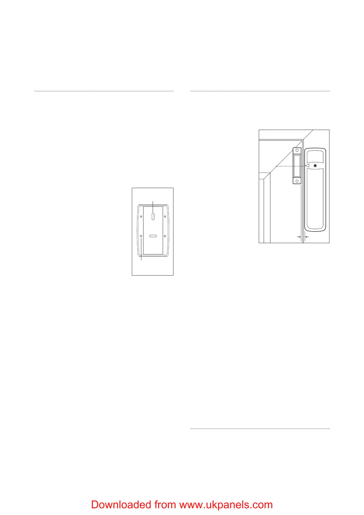
2 Fit as described in
‘Mounting methods’,
mounting the
detector base on the
frame and aligning
the magnet by the
arrow as shown.
• The magnet should
not be more than
8mm from the
detector when the
door is closed.
• Ensure the tamper
switch spring is
positioned so that it
makes contact with
the mounting surface through the tamper
switch aperture.
• If the door contact cannot be mounted on the
door frame, use the HSA3090 multiple
door/window contact accessory kit with a
length of wire to mount the door contact
remotely (see page 17).
• When fitting to a window, fix the magnet to the
moving part and the detector to the frame.
3 Fix the detector on its base and secure with
screw. Test it by opening and closing the door
or window. The light will flash when an open
condition is detected.
4 Remove the detector, put the jumper switch in
the normal ‘off’ position. Screw the detector
back onto its base.
• When the jumper is in the normal ‘off’ position
the indicator light will normally be off. It will
only light if there is a problem, either a low
battery or a tamper condition.
• Ensure the jumper is in the normal ‘off’ position
when testing is finished, otherwise low battery
and tamper conditions will not be shown.
Dummy siren
1 Find a suitable location as previously described.
2 Screw to wall as described for Siren, points 3
and 4.
Installation is complete.
Door/
Window
Frame
Align
8mm (max)
Corner fixing
holes x 4
Surface fixing
holes x 2
 Loading...