EasyManua.ls Logo

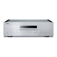
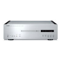
Yamaha CD-S1000 Service Manual

Yamaha CD-S1000
57 pages
To Next Page IconTo Next Page
Page #1 background imageLoading...
Page #1 background image
CONTENTS
TO SERVICE PERSONNEL ...................................... 2–3
PREVENTION OF ELECTROSTATIC DISCHARGE .... 4
FRONT PANEL .............................................................. 5
REAR PANELS .......................................................... 5–7
REMOTE CONTROL PANEL ........................................ 8
SPECIFICATIONS /
参考仕様...................................... 8–9
INTERNAL VIEW ........................................................... 9
DISASSEMBLY PROCEDURES / 分解手順 ........... 10–16
TEST MODE /
テストモード .......................................... 17
UPDATING FIRMWARE /
ファームウェアの書き込み
............................................................................ 18–24
DISPLAY DATA ........................................................... 25
IC DATA ................................................................. 26–28
PIN CONNECTION DIAGRAMS ............................ 29–30
BLOCK DIAGRAM ....................................................... 31
PRINTED CIRCUIT BOARDS................................ 32–40
SCHEMATIC DIAGRAMS ...................................... 41–45
REPLACEMENT PARTS LIST .............................. 47–56
REMOTE CONTROL.................................................... 57
101092
SERVICE MANUAL
SUPER AUDIO CD PLAYER
Copyright © 2008 All rights reserved.
This manual is copyrighted by YAMAHA and may not be copied or
redistributed either in print or electronically without permission.
P.O.Box 1, Hamamatsu, Japan
'08.05
IMPORTANT NOTICE
This manual has been provided for the use of authorized YAMAHA Retailers and their service personnel.
It has been assumed that basic service procedures inherent to the industry, and more specifically YAMAHA Products, are already
known and understood by the users, and have therefore not been restated.
WARNING: Failure to follow appropriate service and safety procedures when servicing this product may result in personal
injury, destruction of expensive components, and failure of the product to perform as specified. For these reasons,
we advise all YAMAHA product owners that any service required should be performed by an authorized
YAMAHA Retailer or the appointed service representative.
IMPORTANT: The presentation or sale of this manual to any individual or firm does not constitute authorization, certification or
recognition of any applicable technical capabilities, or establish a principle-agent relationship of any form.
The data provided is believed to be accurate and applicable to the unit(s) indicated on the cover. The research, engineering, and
service departments of YAMAHA are continually striving to improve YAMAHA products. Modifications are, therefore, inevitable
and specifications are subject to change without notice or obligation to retrofit. Should any discrepancy appear to exist, please
contact the distributor's Service Division.
WARNING: Static discharges can destroy expensive components. Discharge any static electricity your body may have
accumulated by grounding yourself to the ground buss in the unit (heavy gauge black wires connect to this buss).
IMPORTANT: Turn the unit OFF during disassembly and part replacement. Recheck all work before you apply power to the unit.
CD-S1000
CD-S1000
Other manuals for Yamaha CD-S1000

Questions and Answers:

Yamaha CD-S1000 Specifications

General IconGeneral
Frequency range2 - 50000 Hz
Output power description2 +/- 0.3 V
Signal-to-Noise Ratio (SNR)113 dB
Total Harmonic Distortion (THD)0.002 %
Device typeHiFi CD player
Product colorSilver
Disc loading typeTray
Volume controlDigital
Dimensions (WxDxH)137 x 440 x 435 mm
Weight and Dimensions IconWeight and Dimensions
Weight15000 g

Summary

To Service Personnel

Critical Components Information

Details on components with special characteristics requiring exact replacement.

Leakage Current Measurement

Procedure to verify insulation of conductive surfaces after service.

Laser Diode Properties

Prevention of Electrostatic Discharge

Grounding for Electrostatic Breakdown Prevention

Techniques for grounding human body and work table to prevent ESD damage.

Specifications / 参考仕様

Disassembly Procedures / 分解手順

Disassembly Procedures / 分解手順 (continued)

Removal of DVD Traverse Mechanism and Stepping Motor

Steps for removing the DVD traverse mechanism and stepping motor.

Test Mode / テストモード

Starting Test Mode

How to activate the service test mode by pressing specific keys.

Operating Test Mode

Instructions on navigating and viewing information within the test mode.

Updating Firmware / ファームウェアの書き込み

Writing to the Microprocessor

Procedure for updating firmware on the microprocessor.

Preparation and Precautions Before Starting Operation

Steps to prepare the PC and software before starting firmware writing.

Updating Firmware / ファームウェアの書き込み (continued)

Starting FlashSta.exe

Instructions on launching the firmware update utility and selecting options.

Initiating Program Writing

Steps to start the firmware writing process and confirm completion.

Finalizing Firmware Update Process

Procedures to complete the update, disconnect cables, and confirm firmware version.

Writing to the Module Board

Procedure for updating the firmware on the module board.

Completing Module Board Firmware Update

Steps to finish the update, remove the CD, and confirm the new firmware version.

Required Tools

Specifies the need for a firmware CD and its creation process.

Selecting Port and Data for Transmission

How to select the correct COM port and firmware file for the update.

Confirmation of Firmware Version

Verifying the module board firmware update using the test mode.

Operation Procedures

Steps for performing the firmware update using the module board's tray.

Display Data

IC Data

M30302FAPFP (DIGITAL (1) P.C.B.)

Pinout and peripheral functions of the M30302FAPFP microprocessor.

IC Data (continued)

Pin Connection Diagrams

Pin Connection Diagrams (continued)

Block Diagram

Printed Circuit Boards

Printed Circuit Boards (continued)

Schematic Diagrams

DIGITAL (1)

Overall schematic diagram for the Digital (1) section.

Schematic Diagrams (continued)

DIGITAL (2/3)

Schematic diagram covering Digital (2) and (3) sections.

DIGITAL (5)

Schematic diagram for the Digital (5) section.

AUDIO

Schematic diagram for the Audio section, including DACs and amplifiers.

POWER

Schematic diagram for the Power supply section, including regulators and transformers.

Replacement Parts List

Replacement Parts List (continued)

Remote Control

Related product manuals