EasyManua.ls Logo

Yamaha CRX-E400 User Manual

Yamaha CRX-E400
40 pages
To Next Page IconTo Next Page
Page #1 background imageLoading...
Page #1 background image
SERVICE MANUAL
CONTENTS
TO SERVICE PERSONNEL . . . . . . . . . . . . . . . . . . . . 2
FRONT PANELS . . . . . . . . . . . . . . . . . . . . . . . . . . . 2–3
REAR PANELS . . . . . . . . . . . . . . . . . . . . . . . . . . . . . . 3
SPECIFICATIONS . . . . . . . . . . . . . . . . . . . . . . . . . .4–5
INTERNAL VIEW . . . . . . . . . . . . . . . . . . . . . . . . . . . . . 5
DISASSEMBLY PROCEDURES . . . . . . . . . . . . . . . 6–7
TEST MODE . . . . . . . . . . . . . . . . . . . . . . . . . . . . . . . 8–9
AMP ADJUSTMENTS . . . . . . . . . . . . . . . . . . . . . . . . . 9
IC DATA . . . . . . . . . . . . . . . . . . . . . . . . . . . . . . . . 10–12
BLOCK DIAGRAM . . . . . . . . . . . . . . . . . . . . . . . . . . . 13
PRINTED CIRCUIT BOARD . . . . . . . . . . . . . . . . 14–17
PIN CONNECTION DIAGRAM . . . . . . . . . . . . . . . . . 18
SCHEMATIC DIAGRAM . . . . . . . . . . . . . . . . . . . 19–20
DISPLAY DATA . . . . . . . . . . . . . . . . . . . . . . . . . . . . . 20
PARTS LIST . . . . . . . . . . . . . . . . . . . . . . . . . . . . . 21–28
REMOTE CONTROL TRANSMITTER . . . . . . . . . . . .29
SYSTEM CONTROL . . . . . . . . . . . . . . . . . . . . . . 30–38
NX-E400 . . . . . . . . . . . . . . . . . . . . . . . . . . . . . . . . . . . 39
PARTS LIST FOR CARBON RESISTORS . . . . . . . . 40
This manual has been provided for the use of authorized YAMAHA Retailers and their service personnel.
It has been assumed that basic service procedures inherent to the industry, and more specifically YAMAHA Products, are already
known and understood by the users, and have therefore not been restated.
WARNING: Failure to follow appropriate service and safety procedures when servicing this product may result in personal
injury, destruction of expensive components, and failure of the product to perform as specified. For these reasons,
we advise all YAMAHA product owners that any service required should be performed by an authorized YAMAHA
Retailer or the appointed service representative.
IMPORTANT: The presentation or sale of this manual to any individual or firm does not constitute authorization, certification or
recognition of any applicable technical capabilities, or establish a principle-agent relationship of any form.
The data provided is believed to be accurate and applicable to the unit(s) indicated on the cover. The research, engineering, and service
departments of YAMAHA are continually striving to improve YAMAHA products. Modifications are, therefore, inevitable and
specifications are subject to change without notice or obligation to retrofit. Should any discrepancy appear to exist, please contact the
distributor's Service Division.
WARNING: Static discharges can destroy expensive components. Discharge any static electricity your body may have
accumulated by grounding yourself to the ground buss in the unit (heavy gauge black wires connect to this buss).
IMPORTANT: Turn the unit OFF during disassembly and part replacement. Recheck all work before you apply power to the unit.
IMPORTANT NOTICE
100809
SERVICE MANUAL
RX-E400/NX-E400
MINI COMPONENT SYSTEM CRX-E400
The CRX-E400 is composed of the RX-E400 and the CDX-E400.
This service manual is for the RX-E400 (including NX-E400).
For the CDX-E400 service manual, please refer to the following publication numbers :
CDX-E400 100808
RX-E400
Question and Answer IconNeed help?

Do you have a question about the Yamaha CRX-E400 and is the answer not in the manual?

Yamaha CRX-E400 Specifications

General IconGeneral
BrandYamaha
ModelCRX-E400
CategoryStereo System
LanguageEnglish

Summary

TO SERVICE PERSONNEL

Critical Components Information

Information on essential components requiring specific replacement parts.

Leakage Current Measurement

Procedure for verifying insulation integrity after service.

Safety Warnings and Precautions

Important safety notices including chemical content and electrical hazards.

FRONT PANELS

U, C, R, A models

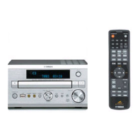
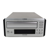
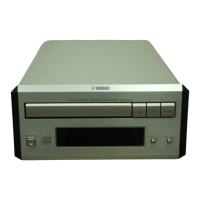
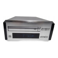
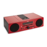
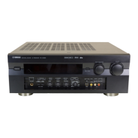
Visual representation of front panel controls for specific models.

FRONT PANELS (continued)

B, G models

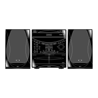
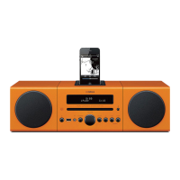
Visual representation of front panel controls for B, G models.

REAR PANELS

U, C models

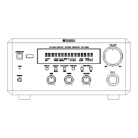
Rear panel connections for U, C models.

B model

Rear panel connections for B model.

R model

Rear panel connections for R model.

G model

Rear panel connections for G model.

A model

Rear panel connections for A model.

SPECIFICATIONS

AUDIO SECTION

Detailed technical specifications for the audio performance.

FM SECTION

Technical tuning and sensitivity details for FM reception.

GENERAL

Power supply, consumption, dimensions, weight, and finish details.

AM SECTION

Technical tuning and sensitivity details for AM reception.

SPECIFICATIONS (continued)

SPEAKER SECTION (NX-E400)

Technical details for the NX-E400 speaker unit.

DIMENSIONS (RX-E400)

Physical dimensions of the RX-E400 unit.

INTERNAL VIEW

Component Identification

Labeled diagram showing the location of major internal components.

DISASSEMBLY PROCEDURES

Removal of Top Cover

Steps to safely remove the main unit's top cover.

Removal of Front Panel

Steps to detach the front panel unit from the chassis.

DISASSEMBLY PROCEDURES (continued)

Servicing Position

Instructions for positioning the unit during service and connecting parts.

TEST MODE

Test Mode Entry and Operation Flow

Procedure for entering and navigating various test modes.

Test Program Mode Function Descriptions

Description of functions available within the test program modes.

TEST MODE (continued)

FACTORY PRESET TABLE

Table listing factory preset frequency data for tuner markets.

AMP ADJUSTMENTS

Confirmation of Idling Current

Procedure to check and adjust the amplifier's idling current.

IC DATA

IC700: M30217M8-A103FP Pinout

Detailed pin assignments for the main microcomputer IC.

IC DATA (continued)

IC700: M30217M8-A103FP Port Functions

Description of functions for various pins of the microcomputer IC.

IC DATA (continued)

IC700: M30217M8-A103FP Port Functions

Description of functions for various pins of the microcomputer IC.

Key Input and Tuner Market Select Resistors

Information on key input resistors and tuner market selection logic.

BLOCK DIAGRAM

System Signal Flow Overview

Diagram illustrating the main signal paths and component interactions.

PRINTED CIRCUIT BOARD (Foil side)

Operation P.C.B. (Lead Type Device View)

Diagram of the operation PCB showing lead-type components.

Semiconductor Location

Identifier for semiconductor component placement on the PCB.

Oscilloscope Measurement Points

Specific points on the PCB for oscilloscope measurements.

PRINTED CIRCUIT BOARD (Foil side) (continued)

Circuit Changes by Market

Details on PCB component variations specific to different market models.

Semiconductor Location

Identifier for semiconductor component placement on the PCB.

PRINTED CIRCUIT BOARD (Foil side) (continued)

Circuit Changes by Market

Details on PCB component variations specific to different market models.

Semiconductor Location

Identifier for semiconductor component placement on the PCB.

PRINTED CIRCUIT BOARD (Foil side) (continued)

Circuit Changes by Market

Details on PCB component variations specific to different market models.

Semiconductor Location

Identifier for semiconductor component placement on the PCB.

PIN CONNECTION DIAGRAM

Integrated Circuits (ICs)

Pin diagrams for various integrated circuit components used in the unit.

Diodes and Transistors

Pin diagrams for diode and transistor components.

SCHEMATIC DIAGRAM (MAIN)

Main Unit Circuit Diagram

Detailed circuit diagram for the main audio receiver unit.

Market-Specific Circuit Changes

Notes on circuit modifications based on regional market variations.

SCHEMATIC DIAGRAM (OPERATION)

Operation Unit Circuit Diagram

Detailed circuit diagram for the operation and control sections.

Display Data and Pin Assignments

Information on display patterns, pin connections, and grid assignments.

PARTS LIST

Electrical Components List

Comprehensive list of electrical parts with part numbers and descriptions.

Abbreviations Used in Parts List

Glossary of abbreviations used in the parts list for clarity.

PARTS LIST (continued)

P.C.B. OPERATION Component List

Specific list of components mounted on the Operation Printed Circuit Board.

PARTS LIST (continued)

P.C.B. MAIN Component List (Page 1)

Detailed list of components for the Main Printed Circuit Board.

PARTS LIST (continued)

P.C.B. MAIN Component List (Page 2)

Detailed list of components for the Main Printed Circuit Board.

PARTS LIST (continued)

P.C.B. MAIN Component List (Page 3)

Detailed list of components for the Main Printed Circuit Board.

EXPLODED VIEW

Unit Assembly Diagrams by Model

Illustrated breakdown of the unit's mechanical assemblies for various models.

MECHANICAL PARTS

Mechanical Components List (Page 1)

List of mechanical parts like chassis, panels, screws, and rivets.

MECHANICAL PARTS (continued)

Mechanical Components List (Page 2)

List of mechanical parts like chassis, panels, screws, and rivets.

REMOTE CONTROL TRANSMITTER

Schematic Diagram

Circuit diagram of the remote control transmitter.

Transmission Format and Key Codes

Details on the data format and hex codes for remote control commands.

SYSTEM CONTROL

Bus System Features and Operation

Overview of the bus system controlling multiple units.

Serial Data Format

Description of the data format used for system communication.

SYSTEM CONTROL (continued)

Main System Operation Descriptions

Explanations of power, function, timer, and dimmer operations.

SYSTEM CONTROL (continued)

Power On/Off Processing Logic

Flowcharts detailing power on/off sequences for receiver and other units.

SYSTEM CONTROL (continued)

Function and Auto Function Selection

Logic for function selection and automatic function adaptation.

SYSTEM CONTROL (continued)

Timer Play and Timer Record Operations

Procedures and logic for timer-based playback and recording.

SYSTEM CONTROL (continued)

Auto Power Off Logic

Flowchart explaining the automatic power-off sequence based on inactivity.

SYSTEM CONTROL (continued)

Auto Power On Logic

Logic for automatic power-on triggered by key operations.

System Control Bus Data Table

Table detailing bus commands, codes, and data parameters for system control.

SYSTEM CONTROL (continued)

Remote Control Function Table

List of remote control functions and their corresponding codes.

SYSTEM CONTROL (continued)

Recording Operation Switch Logic

Logic for switch operations during recording and synchronous modes.

Auto Power On Reception Switch

Information on using the reception switch for auto power-on functionality.

NX-E400 SPEAKER SYSTEM

Exploded View Diagram

Illustrated breakdown of the NX-E400 speaker system.

Speaker System Parts List

List of components for the NX-E400 speaker system.

PARTS LIST FOR CARBON RESISTORS

Carbon Resistor Values and Part Numbers

List of carbon resistor values with corresponding 1/4W and 1/6W part numbers.

Related product manuals