CS6X
11
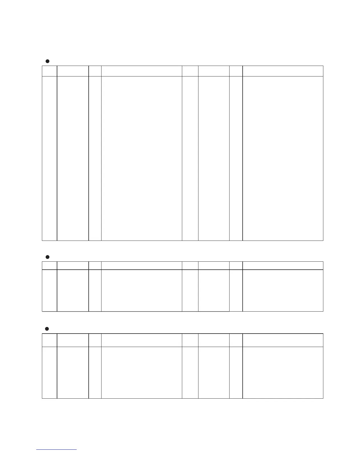
PD63200GS (XM145A00) DAC (Digital to Analog Converter)
PIN
NO.
NAME I/O FUNCTION
PIN
NO.
NAME I/O FUNCTION
1 4/8F I 4/8 Fs selection 9 R. REF Channel R voltage reference
2 D. GND Digital ground 10 L. REF Channel L voltage reference
3 16 BIT I 16 bit/18 bit selection 11 L. OUT O
Channel L output
4 D. VDD Digital power supply 12 A. GND Analog ground
5 A. GND Analog ground 13 WDCK I Word clock
6 R. OUT O Channel R output 14 RSI I Channel R series input
7 A. VDD Analog power supply 15 SI/LSI I
Series input/Channel L series nput
8 A. VDD 16 CLK I Clock
µ
HD63B01Y0RCE0F (XM234A00) CPU (PKS)
PIN
NO.
NAME I/O FUNCTION
PIN
NO.
NAME I/O FUNCTION
1 /NMI I Non-maskable interrupt 33 M1/S8 I Make contact of key receive/
2 E O 34 M0/S7 I Switch receive
3 D# O 35 Vss Ground
4 D O Key scan drive 36 F O
5C# O 37F# O
6CL O 38G O
7 PULL 1 39 G# O Key scan drive
8 PULL 2 40 A O
9 LC.AE//FS I connected to ground 41 A# O
10 /REPEAT I Auto repeat (L:on, H:off) 42 B O
11 /KOF-REQ I Key off request 43 C O
12 SW1 I Switch 1 (L: on, H: off) 44 LC//AE I connected to +5V
13 SW2 I Switch 2 (L: on, H: off) 45 B6/S6 I
14 /IS I Input strobe 46 B5/S5 I
15 /OS I Output strobe 47 B4/S4 I Break contact of key receive/
16 SW3 I Switch 3 (L: on, H: off) 48 B3/S3 I Switch receive
17 SW4 I Switch 4 (L: on, H: off) 49 B2/S2 I
18 DOUT0 O 50 B1/S1 I
19 DOUT1 O 51 B0/S0 I
20 DOUT2 O 52 Se O
21 DOUT3 O 53 Sd O
22 DOUT4 O Data output 54 Sc O Switch drive
23 DOUT5 O 55 Sb O
24 DOUT6 O 56 Sa O
25 DOUT7 O 57 E Not used
26 Vcc Power supply (+5V) 58 Vss Ground
27 Sf O Switch drive 59 XTAL Not used
28 M5/S13 I 60 EXTAL I 8 MHz clock
29 M4/S12 I 61 MP0 I Mode program 0
30 M3/S10 I Make contact of key receive/ 62 MP1 I Mode program 1
31 M2/S9 I Switch receive 63 /RES I Initial clear
32 M1/S8 I 64 /STBY I Stanby-mode signal
JG710069 (XM326B00) DDE1 (DAC Dynamic Range Enhancer)
PIN
NO.
NAME I/O FUNCTION
PIN
NO.
NAME I/O FUNCTION
1 CLK I Master clock 9 SH 0 O N.C.
2 SYW I Sync signal 10 SH 1 O N.C.
3 MIN 1 I Signal input 11 LE O Latch enable for DAC
Power supply
4 MIN 0 I Signal input
Ground
12 V
DD
5 Vss 13 DACO 0 O Output (DAC)
6 SEL 1 I Mode select 14 DACO 1 O Output (DAC)
7 SEL 0 I Mode select 15 DCLK O Clock for DAC
8 SUP I 1 bit shift up input 16 ICN I Initial clear
 Loading...