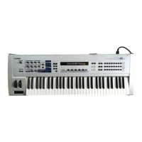
CS6X
10
1 /WRHH O HH write 73 D15 I/O
2 PE14 I/O LCD data 6 input / output 74 D14 I/O Data bus
3 /WRHL O 75 D13 I/O
4 PA21 I MLAN insert detect 76 D12 I/O
5 PE15 I/O LCD data 7 input / output 77 VCC77 - Power supply
6 VSS6 - Ground 78 D11 I/O Data bus
7 A0 O 79 VSS79 - Ground
8 A1 O 80 D10 I/O
9 A2 O Address bus 81 D9 I/O
10 A3 O 82 D8 I/O Data bus
11 A4 O 83 D7 I/O
12 VCC12 - Power supply 84 D6 I/O
13 A5 O Address bus 85 VCC85 - Power supply
14 VSS14 - Ground 86 D5 I/O Data bus
15 A6 O 87 VSS87 - Ground
16 A7 O 88 D4 I/O
17 A8 O 89 D3 I/O
18 A9 O 90 D2 I/O Data bus
19 A10 O 91 D1 I/O
20 A11 O Address bus 92 D0 I/O
21 A12 O 93 VSS93 - Ground
22 A13 O 94 XTAL I Crystal oscillator
23 A14 O 95 MD3 I Mode select
24 A15 O 96 EXTAL I Crystal oscillator
25 A16 O 97 MD2 I Mode select
26 VCC26 - Power supply 98 NMI - Non-maskable interrupt
27 A17 O Address bus 99
VCC99/FWP99
- Power supply
28 VSS28 - Ground 100 PA16 I Encoder 1B input
29 PA20 I Encoder 2A input 101 PA17 I Encoder 1A input
30 PA19 I Encoder 2B input 102 MD1 I Mode select
31 PB2 O Row address strobe 103 MD0 I Mode select
32 PB3 O Column address strobe (low) 104 PLLVCC - PLL power supply
33 PA18 I Host off line detect input 105 PLLCAP - PLL capacitor
34 PB4 O Column address strobe (high) 106 PLLVSS - PLL ground
35 VSS35 - Ground 107 PA15 O CPU clock out
36 PB5 O DRAM read/write 108 /RES - Reset
37 A18 O 109 TIOCOA I
A/D jack insert detect interrupt request input
38 A19 O Address bus 110 PE1 I Smart MINS
39 A20 O 111 PE2 I Model detection
40 VCC40 - Power supply 112 VCC112 - Power supply
41 A21 O Address bus 113 PE3 I Smart busy input
42 VSS42 - Ground 114 PE4 I
MLAN reset interrupt request input
43 /RD O Read 115 PE5 O 1M clock out
44 /WDTOVF - Not used 116 PE6 I Model detection
45 D31 I/O Data bus 117 VSS117 - Ground
46 D30 I/O 118 AN0 I
47 /WRH O High write 119 AN1 I
48 WRL O Low write 120 AN2 I Analog input
49 /CS1 O Chip Select 1 121 AN3 I
50 CS0 O Chip Select 0 122 AN4 I
51 PA9 I MLAN MIDI interrupt request 123 AN5 I
52 PA8 I Interrupt request 124 AVSS - Analog ground
53 /CS3 O Chip select 3 125 AN6 I Analog input
54 /CS2 O Chip select 2 126 AN7 I
55 VSS55 — Ground 127 AVREF - Analog reference voltage
56 D29 I/O 128 AVCC - Analog power supply
57 D28 I/O 129 VSS129 - Ground
58 D27 I/O Data bus 130 RXD0 I MIDI input
59 D26 I/O 131 TXD0 O MIDI output
60 D25 I/O 132 /IRQ0 I
Plug in sireal interrupt request input
61 VSS61 - Ground 133 RXD1 I HOST input
62 D24 I/O Data bus 134 TXD1 O HOST output
63 VCC63 - Power supply 135 VCC135 - Power supply
64 D23 I/O 136 /IRQ1 I MLAN MIDI interrupt input
65 D22 I/O 137 PE7 I Smart Vprt Input
66 D21 I/O 138 PE8 I/O LCD data 0 input / output
67 D20 I/O Data bus 139 PE9 I/O LCD data 1 input / output
68 D19 I/O 140 PE10 I/O LCD data 2 input / output
69 D18 I/O 141 VSS141 - Ground
70 D17 I/O 142 PE11 I/O LCD data 3 input / output
71 VSS71 - Ground 143 PE12 I/O LCD data 4 input / output
72 D16 I/O Data bus 144 PE13 I/O LCD data 5 input / output
PIN
NAME I/O FUNCTION
NO.
PIN
NAME I/O FUNCTION
NO.
HD64F7045F28 (XW419A00) CPU
LSI PIN DESCRIPTION

 Loading...