JK, DM, PNA
Ref No.
72
62
42
92
PARTS NAME
Bind Head Tapping Screw-B 3.0 X 6 MFZN2BL
Bind Head Tapping Screw-B 3.0 X 8 MFZN2BL
Bind Head Tapping Screw-B 3.0 X 8 MFZN2BL
Bind Head Tapping Screw-B 3.0 X 6 MFZN2BL
PARTS No.
EP600230
EP600190
EP600290
EP600230
Q'ty
4
4
4
6
Fig.
2
2
2
2
Circuit Board & Unit
KEYBOARD Ass'y
Touch Volume
Wheel Ass'y
PS Ass'y
Ref No.
322
122
32
PARTS NAME
Bonding Tapping Screw-B 3.0 X 10 MFZN2BL
Bind Head Tapping Screw-B 3.0 X 6 MFZN2BL
Remove the DM circuit board with the DM sheeld plate.
Bind Head Tapping Screw-B 3.0 X 10 MFZN2BL
PARTS No.
VQ049800
EP600230
EP600230
Q'ty
9
7
11
Fig.
2
3
4
Circuit Board & Unit
JK
DM
PNA
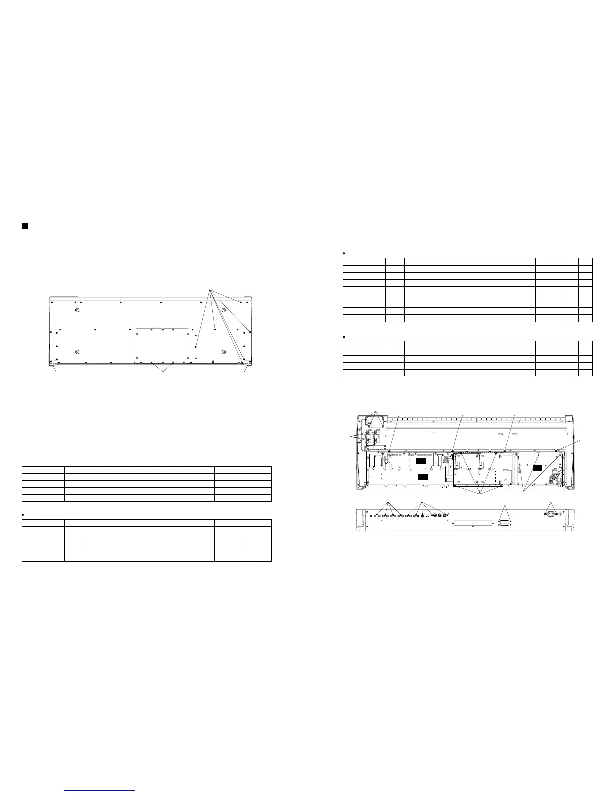
〈
BOTTOM VIEW
〉
〈
REAR VIEW
〉
1. Bottom Assembly
Remove the thirty-five (35) screws marked [104], the
two (2) corner plates, marked [102], and the two (2)
coin screws marked [106]. The botton assembly can
then be removed.
2. Circuit Boards and Units
After removing the bottom assembly, remove the
circuit board and unit, following the procedure in the
below table.
SM, RV, Display Ass'y
Ref No.
112
62
322
122
52
22
PARTS NAME
Bind Head Tapping Screw-B 3.0 X 6 MFZN2BL
Bind Head Tapping Screw-B 3.0 X 8 MFZN2BL
Bonding Tapping Screw-B 3.0 X 10 MFZN2BL
Bind Head Tapping Screw-B 3.0 X 6 MFZN2BL
Remove the DM circuit board with the DM sheeld plate.
Bind Head Tapping Screw-B 3.0 X 6 MFZN2BL
Bind Head Tapping Screw-B 3.0 X 6 MFZN2BL
PARTS No.
EP600230
EP600190
VQ049800
EP600230
EP600230
EP600230
Q'ty
5
2
9
7
8
4
Fig.
2
2
2
3
4
4
Circuit Board & Unit
PLG Support Brecket
SM
JK
DM
RV
Display Ass'y
Fig.2
Ref No.
92
112
62
42
PARTS NAME
Bind Head Tapping Screw-B 3.0 X 6 MFZN2BL
Bind Head Tapping Screw-B 3.0 X 6 MFZN2BL
Bind Head Tapping Screw-B 3.0 X 8 MFZN2BL
Bind Head Tapping Screw-B 3.0 X 8 MFZN2BL
PARTS No.
EP600230
EP600230
EP600190
EP600190
Q'ty
6
5
2
11
Fig.
2
2
2
4
Circuit Board & Unit
PS Ass'y
PLG Support Brecket
SM
PNB
PNB
 Loading...