EasyManuals Logo

Yamaha DBR Series Service Manual

Yamaha DBR Series
109 pages
To Next Page IconTo Next Page
To Previous Page IconTo Previous Page
Page #103 background imageLoading...
Page #103 background image
HIJKL GFEDCBA
1
2
3
4
5
6
7
8
AMPS CIRCUIT DIAGRAM 001 (DBR10/DBR12/DBR15)
28CC1-2001134270-1
DBR10/DBR12/DBR15
5
: Not installed(未実装)
1
WARNING
Components having special characteristics are marked and must be replaced with
parts having specificationequal to those originally installed.
安全上の注意
印の部品は安全維持すに重要な部品です交換す場合は安全の
必ず指定の部品ご使ださい
REGULATOR +15V
REGULATOR +15V
REGULATOR -15V
REGULATOR +15V
Power
Transformer
RESONANT
CONTROLLER
to SUBL
(
ACIN
)
-
W301
(
L/N
)
3DJH%%!
to DC FAN
to VSL - CN901
3DJH%!
to DSP - CN505
3DJH%!
J
U,T
E,B,K,O
P
J
U,T
E,B,K,O
P
(P destination only)

Other manuals for Yamaha DBR Series

Questions and Answers:

Question and Answer IconNeed help?

Do you have a question about the Yamaha DBR Series and is the answer not in the manual?
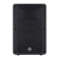
Yamaha DBR Series Specifications

General IconGeneral
TypePowered Speaker
Amplifier ClassClass-D
InputsXLR, 1/4" TRS, RCA
OutputsXLR
Enclosure MaterialPlastic
Mounting OptionsPole mount
Coverage angle90° x 60°
I/O ConnectorsXLR, 1/4" TRS, RCA
Woofer Size12"
Tweeter Size1.4"
ProtectionOvercurrent protection

Related product manuals