18
DBR10/DBR12/DBR15
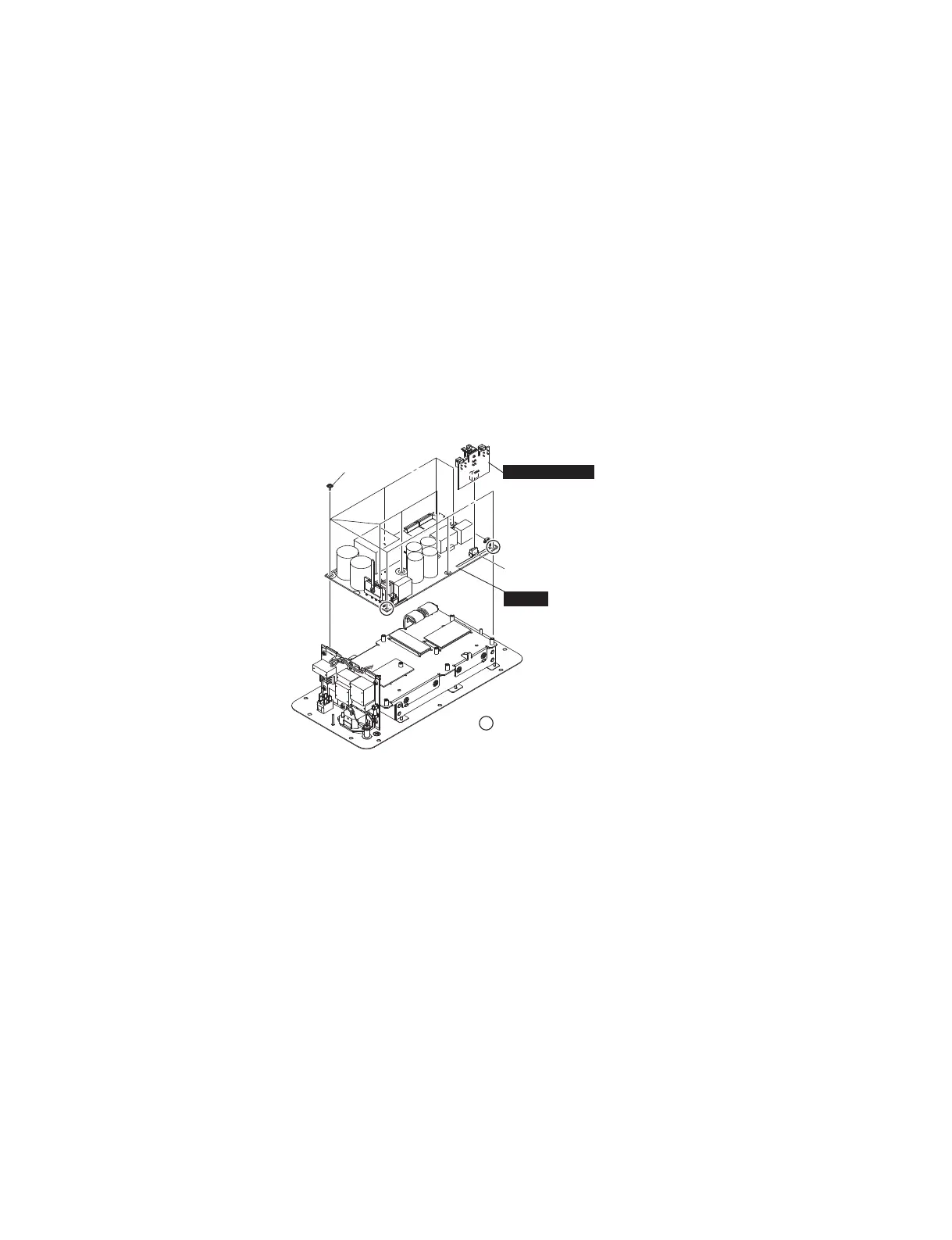
C-3. SUBL (SP OUT) Circuit Board
(Time required: About 1 minute)
C-3-1 Remove the shield AMP assembly. (See procedure C-2.)
C-3-2 Remove the SUBL (SP OUT) circuit board by pulling
it from the connector CN202 of the AMPS circuit board.
(Fig. C-3)
C-4. AMPS Circuit Board
(Time required: About 3 minutes)
C-4-1 Remove the shield AMP assembly. (See procedure C-2.)
C-4-2 Remove the SUBL (SP OUT) circuit board.
(See procedure C-3.)
C-4-3 Remove the ten (10) screws marked [300]. The AMPS
circuit board can then be removed. (Fig. C-3)
* When installing the AMPS circuit board, fi rst tighten the
two (2) priority screws in order as shown in Fig. C-3.
C-5. SUBL (ACIN) Circuit Board
(Time required: About 3 minutes)
C-5-1 Remove the shield AMP assembly. (See procedure C-2.)
C-5-2 Remove the three (3) screws marked [170] and the
screw marked [340]. The SUBL (ACIN) circuit board
can then be removed. (Fig. C-4)
*
When installing the SUBL (ACIN) circuit board, fi rst tighten
the two (2) priority screws in order as shown in Fig. C-4.
C-5-3 Remove the fi ve (5) nylon rivets white marked [110] .
The cover ACIN can then be removed. (Fig. C-4)
C-5-4 Remove the screw marked [70] . The angle acin can
then be removed. (Fig. C-4)
*
The cover ACIN, angle ACIN and the bracket AC inlet
are not parts of the SUBL (ACIN) circuit board. When
replacing the SUBL (ACIN) circuit board, remove from
the SUBL (ACIN) circuit board and install them to the
new SUBL (ACIN) circuit board. (Fig. C-4)
*
Change the nonwoven fabric cloth when replacing the
SUBL (ACIN) circuit board.
*
When installing the screw marked [340], tighten so that
the terminal lug points within the 90-degree range as
shown in Fig. C-4
C-3. SUBL(SPOUT)シート
(所要時間:約1分)
C-3-1 シールドAMP組立を外します。(C-2項参照)
C-3-2 SUBL(SPOUT)シートをAMPSシートのCN202の
コネクターから引き抜いて外します。(図C-3)
C-4. AMPSシート
(所要時間:約3分)
C-4-1 シールドAMP組立を外します。(C-2項参照)
C-4-2 SUBL(SPOUT)シートをを外します。(C-3項参照)
C-4-3 [300]のネジ10本を外して、AMPSシートを外しま
す。(図C-3)
※ AMPSシートを取り付け時には、優先ネジ2本を図に示
す順番で先に締めてください。(図C-3)
C-5. SUBL(ACIN)シート
(所要時間:約3分)
C-5-1 シールドAMP組立を外します。(C-2項参照)
C-5-2 [170]のネジ3本と[340]のネジ1本を外して、SUBL
(ACIN)シートを外します。(図C-4)
※ SUBL(ACIN)シートを取り付け時には、優先ネジ2本を
図に示す順番で先に締めてください。(図C-4)
C-5-3 [110]のプラスチックリベット5本を外して、カ
バー ACINを外します。(図C-4)
C-5-4 [70]のネジ1本を外して、取付板ACINを外します。
(図C-4)
※ カバー ACIN、取付板ACIN、ブラケットACインレット
は、SUBL(ACIN)シートの構成部品ではありません。
SUBL(ACIN)シートを交換する際には、SUBL(ACIN)シー
トから取り外して、新しいSUBL(ACIN)シートに取り付
けてください。(図C-4)
※ 不織布は、SUBL(ACIN)シート交換時に新しい物に交換
してください。
※ [340]のネジを取り付けるときは、ターミナルラグの向
きが、図の通り90度の範囲となるように締めてくださ
い。(図C-4)
>@
&1
w
q
35,25,7<6&5(:
(優先ネジ)
SUBL
(
SP OUT
)
AMPS
Fig. C-3
(図C-3)
 Loading...